Segmentation Process Overview
flowchart LR

S["Original image"] --> E1["Segmentation or detection"]
E1 --> E2["{Binary mask}<br/>Foreground = 1<br/>Background = 0"]
E2 --> E3{"What mask defect exists?"}

E3 --> E4["Need larger regions<br/>or connected gaps"]
E4 --> E41["{Dilation}<br/>Grow foreground"]

E3 --> E5["Need a safe interior<br/>or remove thin parts"]
E5 --> E51["{Erosion}<br/>Shrink foreground"]

E3 --> E6["Small foreground blobs"]
E6 --> E61["{Opening}<br/>Erosion then dilation"]

E3 --> E7["Small holes or breaks"]
E7 --> E71["{Closing}<br/>Dilation then erosion"]

E41 --> E8["Cleaned mask"]
E51 --> E8
E61 --> E8
E71 --> E8
Links: Dilation · Erosion · Opening · Closing · Choosing Morphological Operations
A binary mask assigns each pixel to one of two groups:
-
Foreground (
1): Pixels that belong to the selected object -
Background (
0): All other pixels
Key idea
A binary mask records where the object is. It stores object membership rather than the original colour or brightness.
Example
For a crack in a road:
-
The crack is foreground
-
The remaining road surface is background
Thresholding, covered in Point Processing, is one method for creating a binary mask.
Reading a Mask
Each number represents one pixel:
0 0 0 0 0
0 1 1 1 0
0 1 1 1 0
0 0 0 0 0
The six 1 pixels form a rectangular foreground region. The surrounding 0 pixels are background.
Foreground is a choice
Foreground means the object selected for the task. A dark crack can be foreground even when the road is brighter.
Connection to Morphology
Morphology changes the shape of the foreground region to:
- Remove small unwanted regions
- Fill small holes
- Connect gaps between object parts
Structuring Elements (Probe)
A small shape can be used to probe the foreground. A shapes are:
- square
- cross
- horizontal line
- vertical line
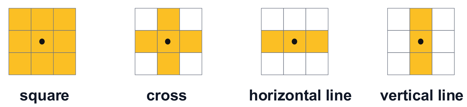
The yellow cells describes which neighbouring locations are tested, while the middle cell with a dot is the anchor point.
We usually choose a shape that we want to repair or keep.
Anchor Point and Translation
The anchor point fixes the position of the structuring element on the image. Moving the anchor moves the entire probe by the same amount. This movement is called translation.
For a centred cross probe:
. X .
X A X
. X .
Here, A is the anchor and an active cell. Each X is another active cell. Each . is outside the probe shape.
Which cells are tested?
This cross uses the centre, top, bottom, left, and right positions. The four corner positions are ignored in dilation and erosion.
Choosing the Shape and Size
Common choices:
| Probe | Positions included |
|---|---|
| Horizontal line | Positions along a row |
| Vertical line | Positions along a column |
| Centred 3-by-3 cross | Centre and four direct neighbours |
| Centred 3-by-3 square | Centre and all eight neighbours, including diagonals |
- Shape controls which neighbouring positions are used
- Size controls how far the probe extends from its anchor
- The operation determines how those positions change the output
Match the probe to the task
A horizontal line probe can repair a horizontal gap without adding vertical thickness during dilation. A square probe also expands the foreground vertically.
Dilation expands the foreground of a binary mask using a structuring element. It can connect small gaps and thicken thin structures.