Introduction
A wrist force sensor sits between the robot arm and the tool. It changes the forces and moments at the hand into small deflections that you can measure. It uses strain gauges to measure the deflection of its structure.
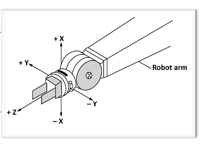
The required performance is:
- compact design
- high stiffness
- linearity
- low hysteresis and internal friction
How it works
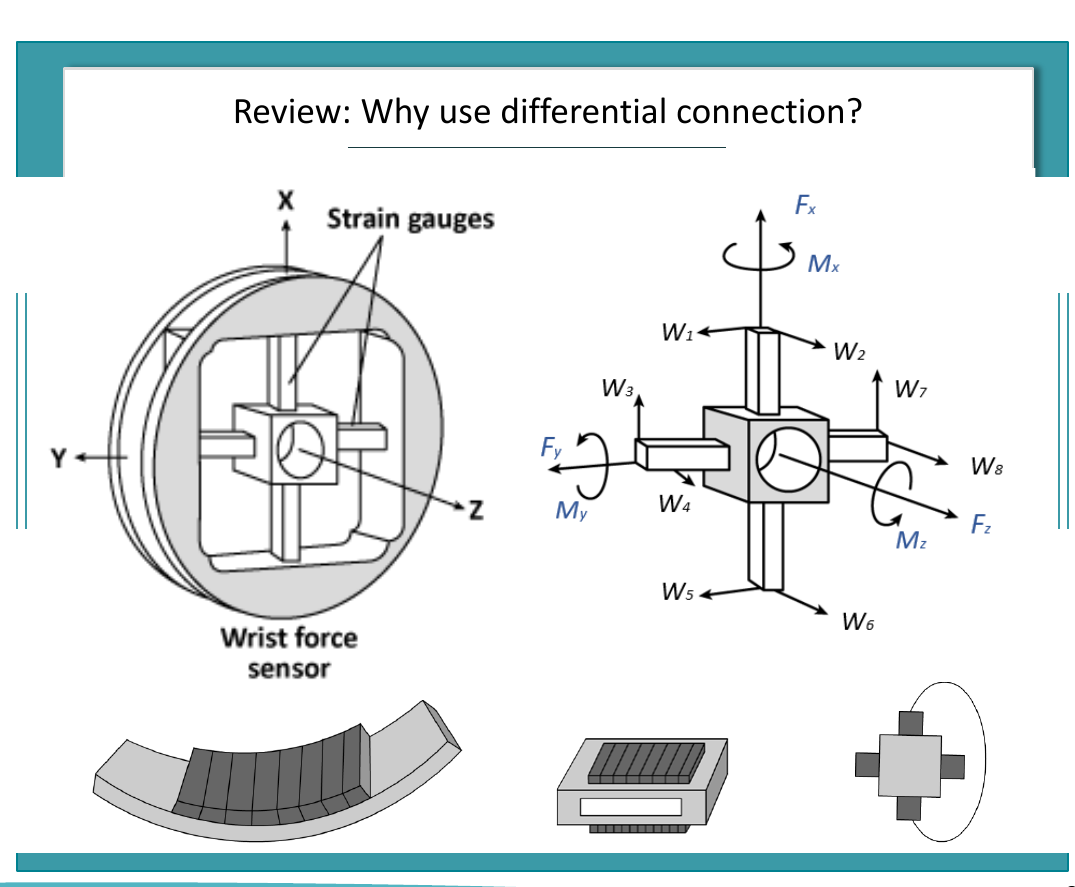
- the sensor is one solid piece of metal, usually aluminium
- it has four deflection bars, with eight pairs of strain gauges on them
- there is one gauge on each side of a deflection bar
- the gauges on opposite sides are wired differentially to a potentiometer circuit. The output voltage is proportional to the force component normal to the plane of the gauges
Resolved force matrix
The sensor gives eight raw readings. Software changes them into three forces and three moments in the sensor frame, with a resolved force matrix (also called the sensor calibration matrix):
where:
- is the force and moment vector
- is the vector of raw readings in volts
If the coupling between the gauges is very small, many are zero:
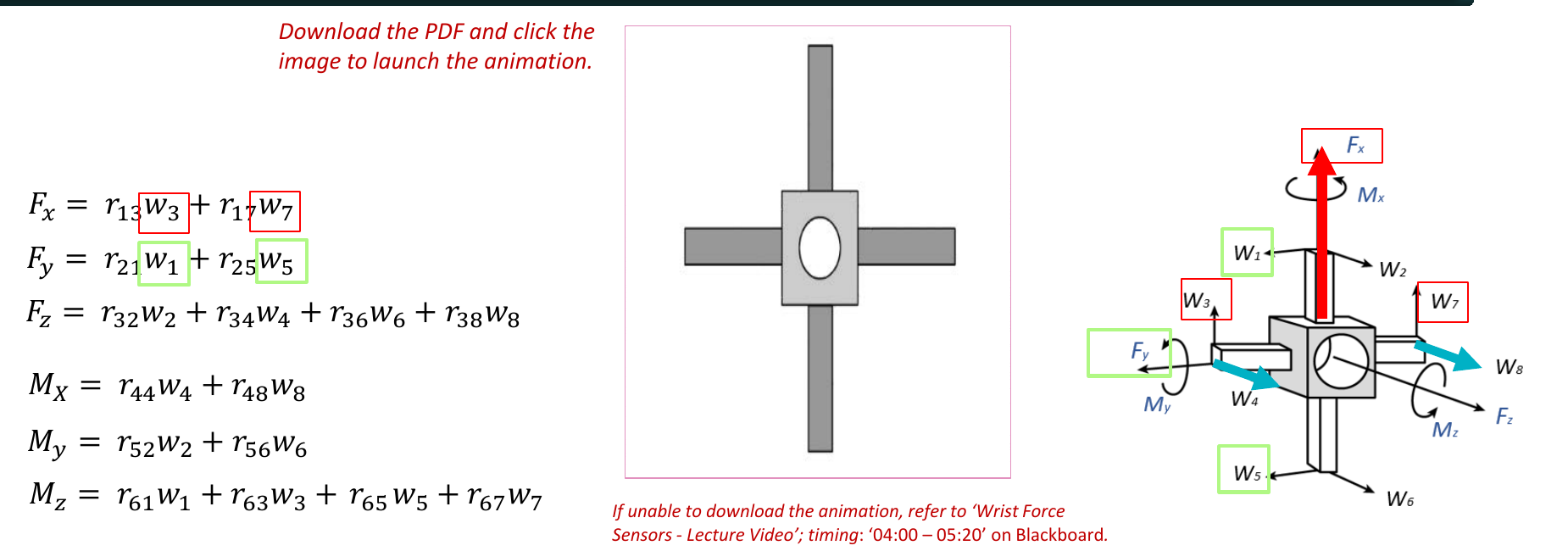
In practice there is often coupling, which can cause up to 5 percent error in the force calculation.
Calibration
The aim of calibration is to find the 48 unknown elements of from test data.
- Apply known forces (inputs) by placing known weights along the axes of the sensor frame
- Measure the voltages (outputs)
- Find the matrix that satisfies
Then find with the pseudoinverse and a least squares fit: