Source
Adapted from my own handwritten and hand-typed notes from Year 1 to Year 3 of my EEE degree
Case study applying the OCTC and SCTC methods to a common-source amplifier with source resistance , coupling capacitor , gate resistor , drain resistor , load and load capacitance .
Step 1: Label the Capacitors
Capacitors present: , , , , . is left out because the source and body are both at , which is AC ground.
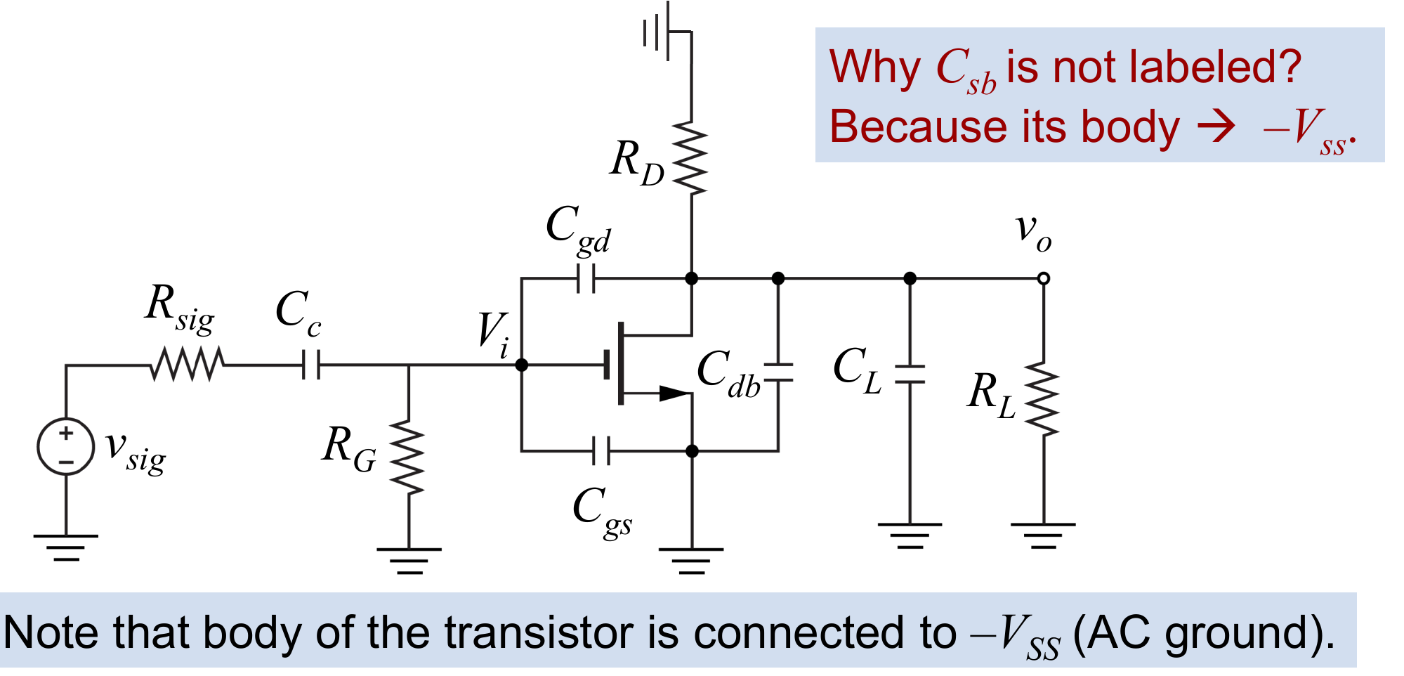
High Frequency: Classify
Results:
- shorted gives better signal sharing, so it is a helper and stays shorted
- shorted forces , so it is a troublemaker
- shorted ties input to output and the gain drops to about 1, so it is a troublemaker
- and shorted force , so they are troublemakers (and are in parallel)
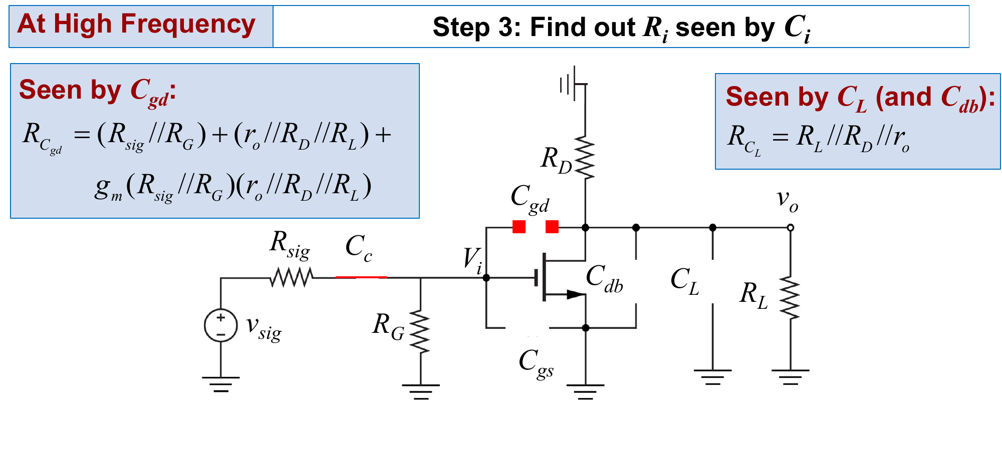
High Frequency: Resistances
Let and :
The result comes from a test current into the gate-drain branch: and , so .
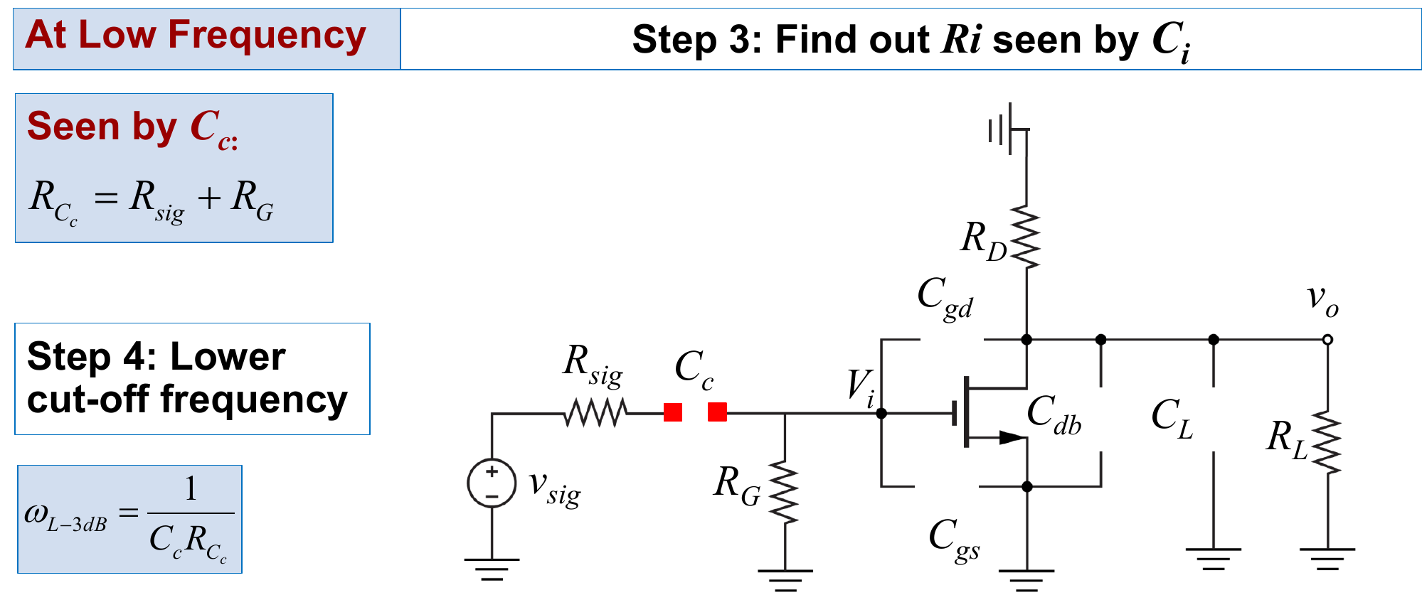
Low Frequency
Only is a troublemaker (opening it isolates the input). All the others are opened. The resistance seen by is
Worked Example
kΩ, kΩ, mS, pF, pF, pF:
- kΩ
- time constants: ns, ns and ns, total ns
- Mrad/s, so MHz
The small gives the largest time constant because its resistance is multiplied by the gain.
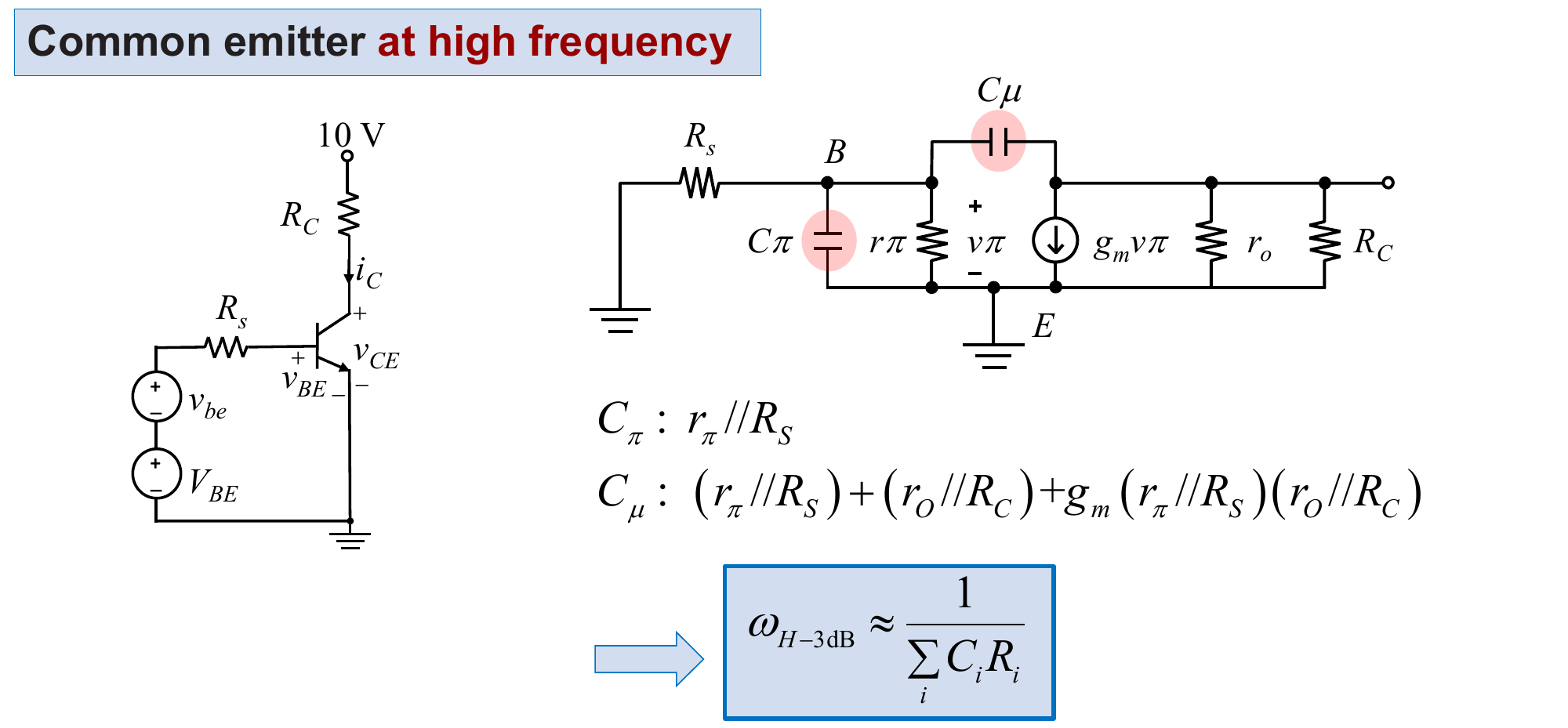
BJT Common Emitter
Same method with and :
Two-Stage Amplifier
For two cascaded C-S stages ( driving , loads and ):
- : , and :
- : , and :
- :
- :
Then as in the OCTC and SCTC Methods.