Source
Adapted from my own handwritten and hand-typed notes from Year 1 to Year 3 of my EEE degree
The clean transistor symbol hides capacitors that come from the physical structure. Some come from the device itself, others from coupling between interconnect wires. These parasitics set the high-frequency limit of an amplifier.
MOSFET Capacitances
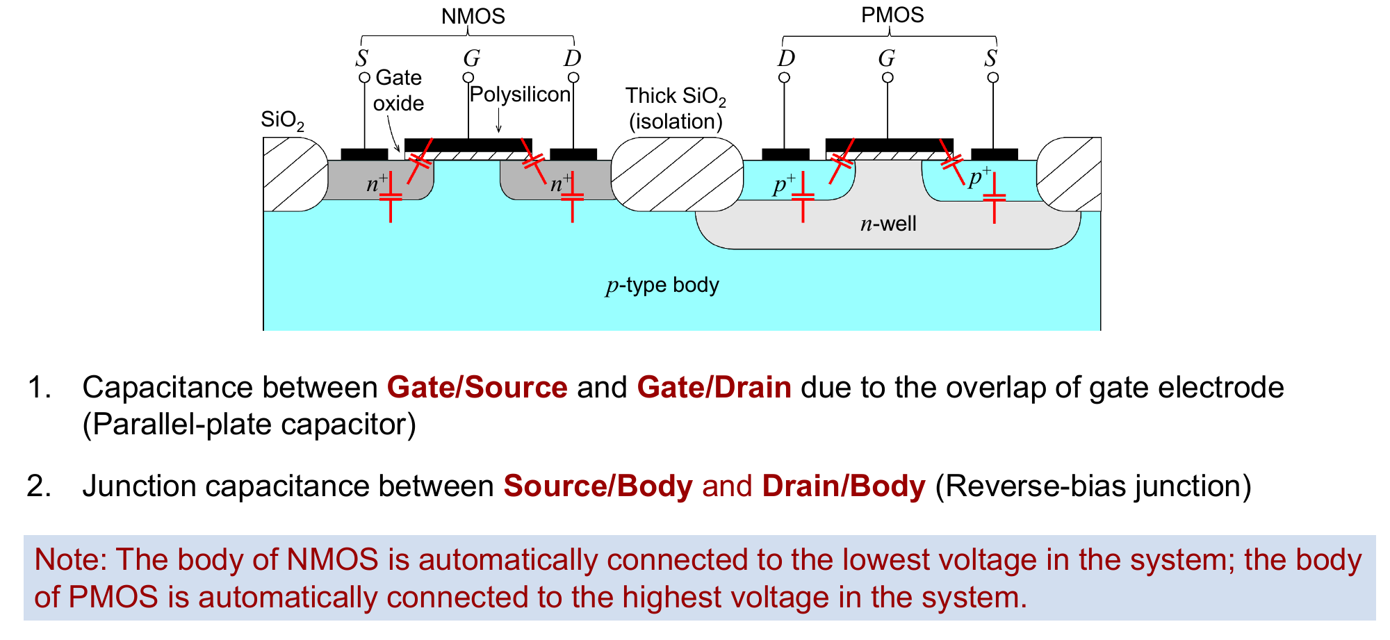
Types:
- and : the gate electrode overlaps the source and drain through the thin oxide, so they are parallel-plate capacitors
- and : the source and drain diffusions form reverse-biased pn junctions with the body, so they are junction capacitances
Body connection:
- the body of an NMOS is tied to the lowest voltage in the circuit
- the body of a PMOS is tied to the highest voltage in the circuit
- if the source sits at the same AC potential as the body, is shorted and can be left out
BJT Capacitances
In the hybrid-pi model at high frequency:
- sits across base and emitter, in parallel with
- bridges base and collector
Which Ones Matter
Rules:
- a capacitor from an internal node to ground (for example , , ) shorts that node at high frequency and kills the signal there
- a capacitor between input and output (for example , ) is the most harmful: the resistance it sees includes a times term, so its time constant is multiplied by roughly the stage gain (the Miller effect)
How these capacitances combine into for a real stage is worked out in Common-Source Amplifier Frequency Response.