Introduction
An incremental encoder is the common way to monitor joint position, because it costs less than an absolute encoder. It counts pulses as the disk turns, so it measures a change in position and not the absolute position.
How it works
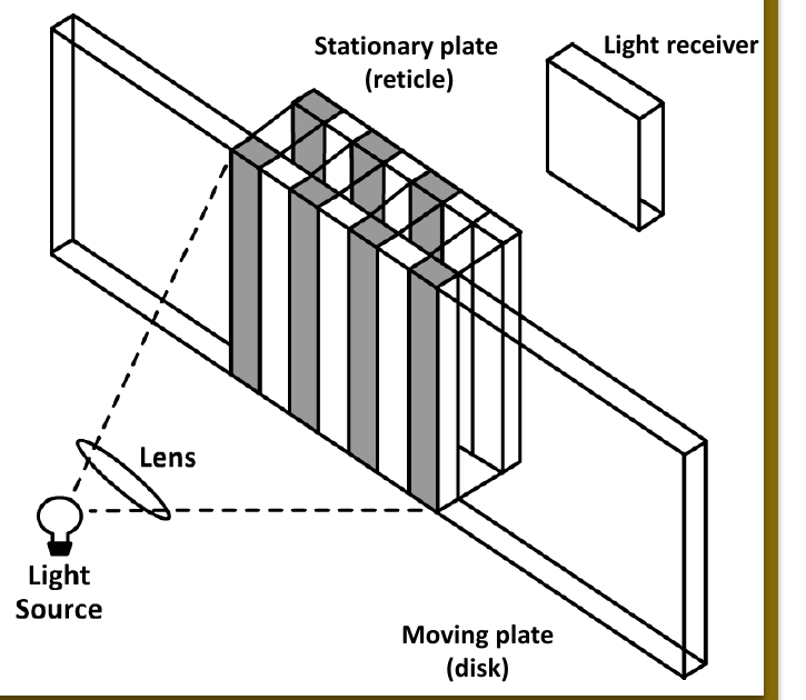
The encoder has a disk, an LED light source and a set of light receivers.
- the thin circular disk has one track of radial lines
- the disk turns with the shaft, and each line blocks the light to the photodetector as it passes
- a stationary plate (reticle) is in front of the receiver. Its slits direct the light from about 20 lines on to one photodetector
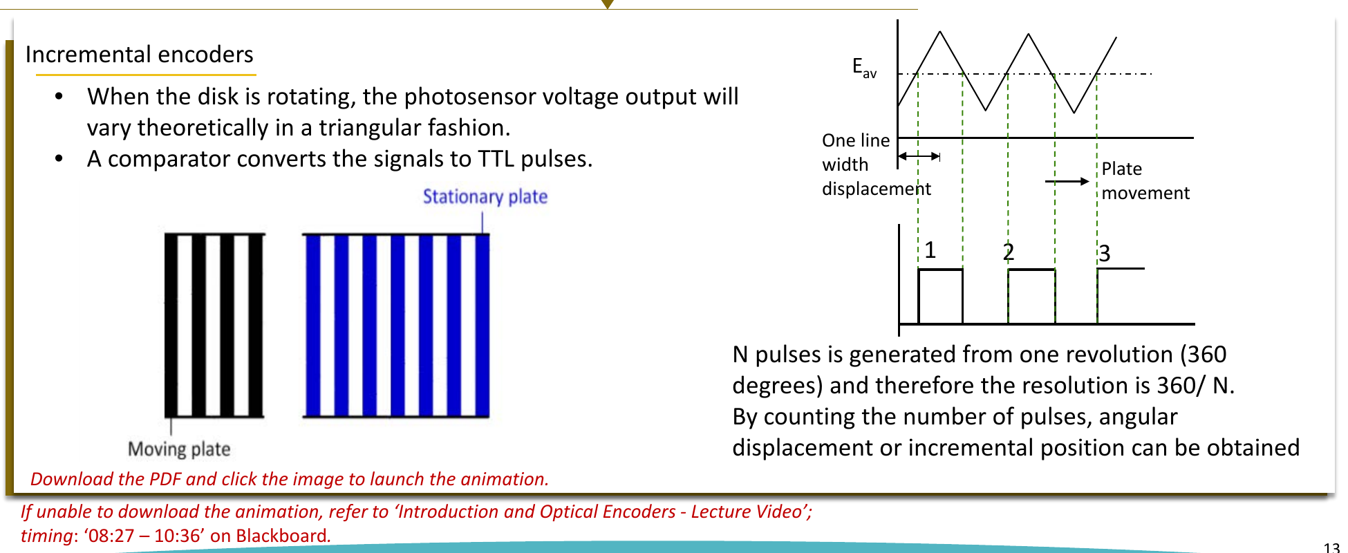
When the disk turns, the photosensor voltage changes in a triangular shape. A comparator changes this signal into TTL pulses. One revolution gives pulses, so:
You count the pulses to get the angular displacement.
Problems with one light sensor
- the width of the pulses changes with the light intensity at the detector
- it cannot find the direction of rotation
Solution with more light sensors
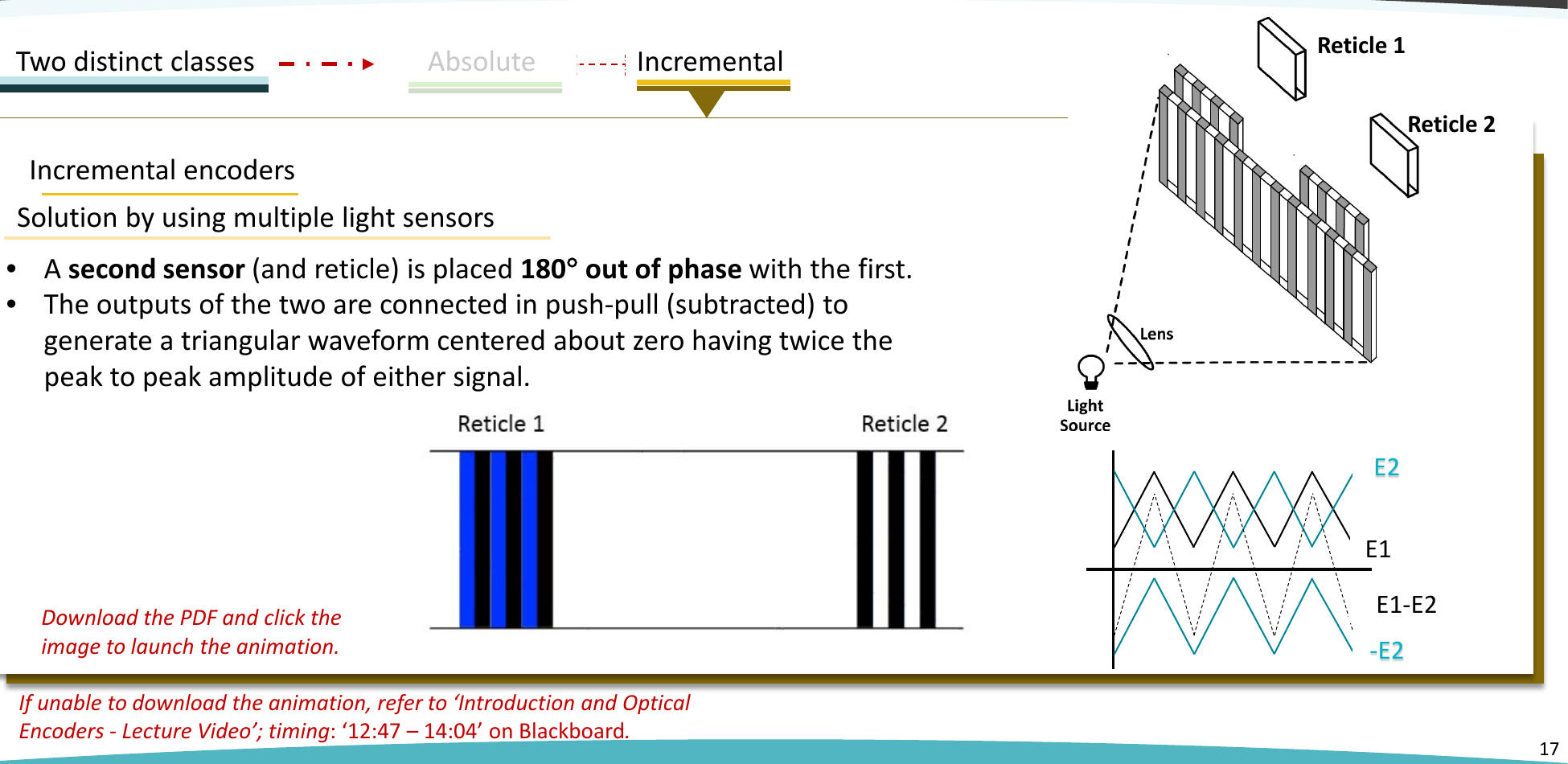
Push-pull pair (180 degrees): a second sensor and reticle are placed out of phase with the first. The two outputs are subtracted. The result is a triangular wave centred on zero with twice the peak to peak amplitude. This removes the effect of light intensity.
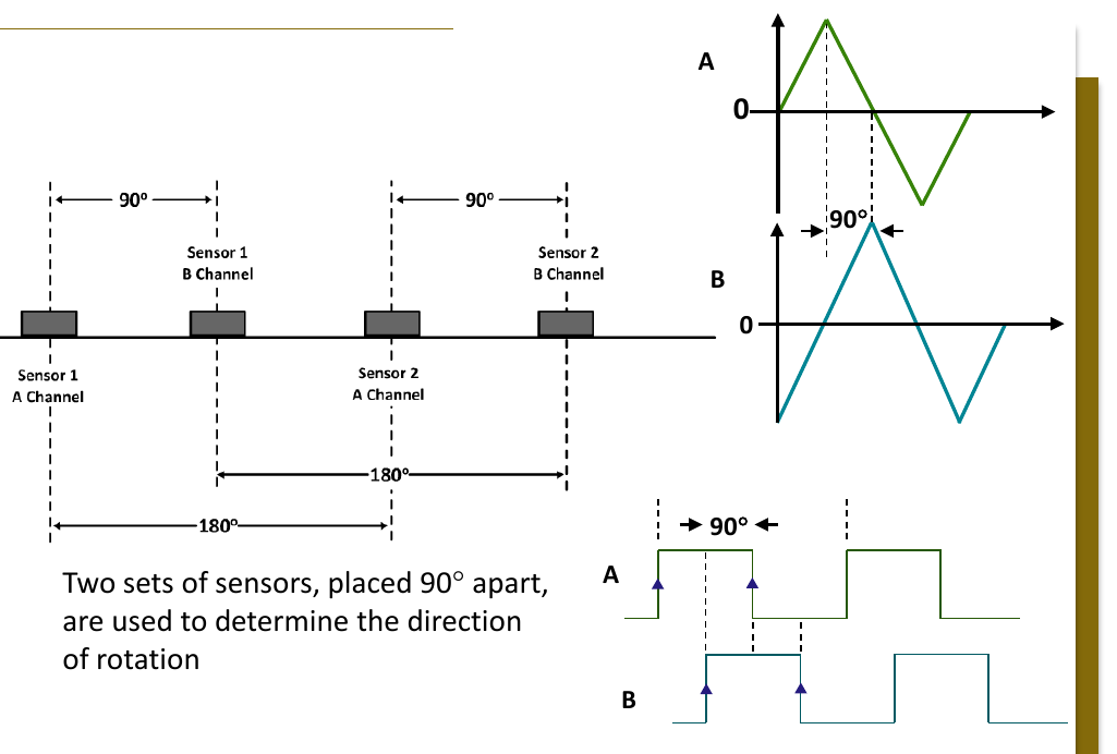
Quadrature pair (90 degrees): a second set of sensors is placed (electrical) out of phase with the first. The first set gives channel A and the second set gives channel B.
- if A leads B, the disk turns in one direction
- if A lags B, the disk turns in the other direction
Higher resolution
Each line gives four edges (transitions) on channels A and B. If you count all the edges, the resolution is four times better: