Introduction
To design a linear controller in Motion Control Schemes, you need a transfer function for one joint. A common actuator in industrial robots is the armature controlled DC motor. The motor shaft turns the link through a gear train.
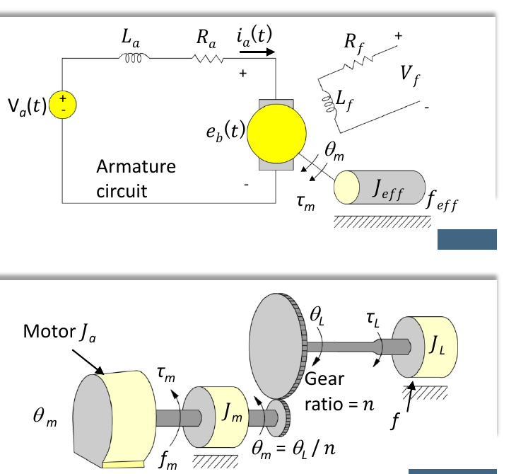
Mechanical part
The gear train links the motor angle to the load (joint) angle with gear ratio :
The torque at the motor shaft is the torque for the motor plus the load torque referred to the motor:
where:
- , are the moment of inertia and viscous friction of the load
- , are the moment of inertia and viscous friction of the motor
Combine these:
Laplace transform:
Electrical part
Kirchhoff's voltage law on the armature circuit:
The back emf is proportional to the motor speed, . So:
The motor torque is proportional to the armature current, , where is the motor torque constant.
Transfer function
Put the electrical and mechanical parts together:
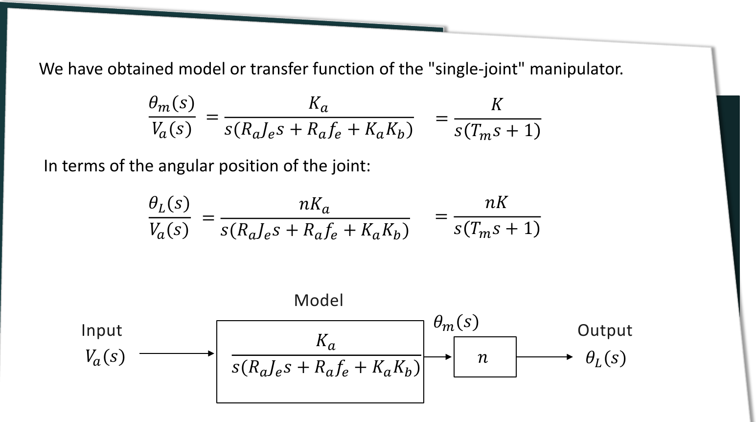
This is a third order system, which is hard to work with. The electrical time constant is much smaller than the mechanical time constant, so you can neglect :
- motor gain constant:
- motor time constant:
In terms of the joint angle :
In the later slides, and are written as and :
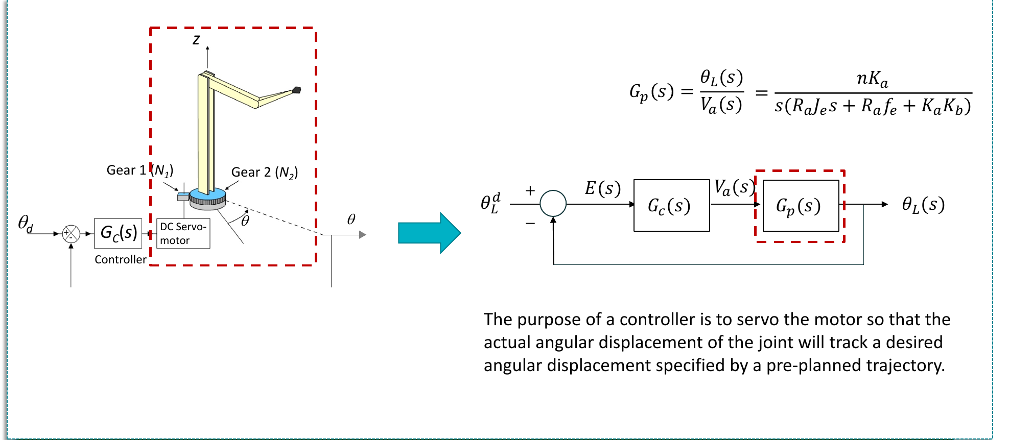
Note
Slides 25 and 26 write in the numerator. The correct constant is , because the motor torque is . Slide 27 and the later slides use .