Introduction
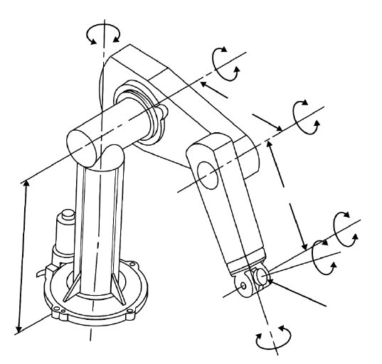
This note shows the control system of the PUMA industrial robot, as an example of a real controller. The PUMA has six joints. Each joint uses independent joint control, as in Motion Control Schemes.
How it works
The controller has two levels.
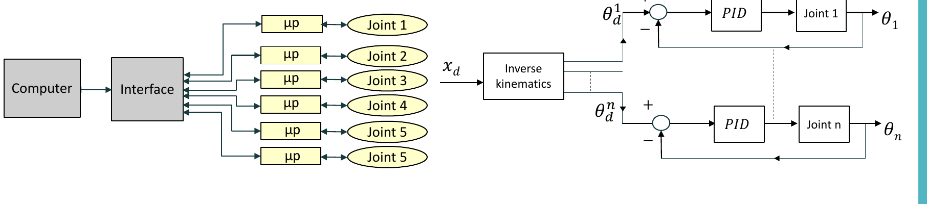
Top level: the computer (master)
- it sends commands to six microprocessors, one for each joint
- it interprets the program commands (robot programming language) one by one
- it does the inverse kinematics, plans the trajectory through the via points, and makes a new set point for the joint controllers at each sampling time
- it connects to peripherals, such as the terminal and the teach pendant
Bottom level: the joint microprocessors
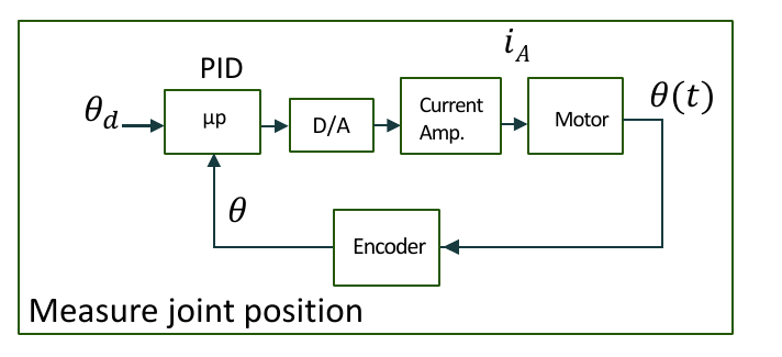
- each microprocessor controls one joint with a PID control law
- each joint has an incremental optical encoder, which gives the current joint position
- there are no tachometers. The joint velocity comes from the difference of joint positions on each servo cycle
- the microprocessors run at a faster sampling time than the computer
- they interpolate the desired set point, calculate the servo error, calculate the PID law and send a new torque command to the motors
- DACs change the digital torque commands into analogue signals for the DC motors
flowchart LR
    PC["Computer<br/>IK and trajectory"] --> IF["Interface"]
    IF --> UP["μP per joint<br/>PID law"]
    UP --> DA["D/A"] --> AMP["Current amp"] --> M["Motor"]
    M --> ENC["Encoder"] --> UP