Source
Adapted from my own handwritten and hand-typed notes from Year 1 to Year 3 of my EEE degree
A real amplifier has a flat gain only over a band of frequencies. Outside it, capacitors make the gain roll off on both sides.
Three Bands
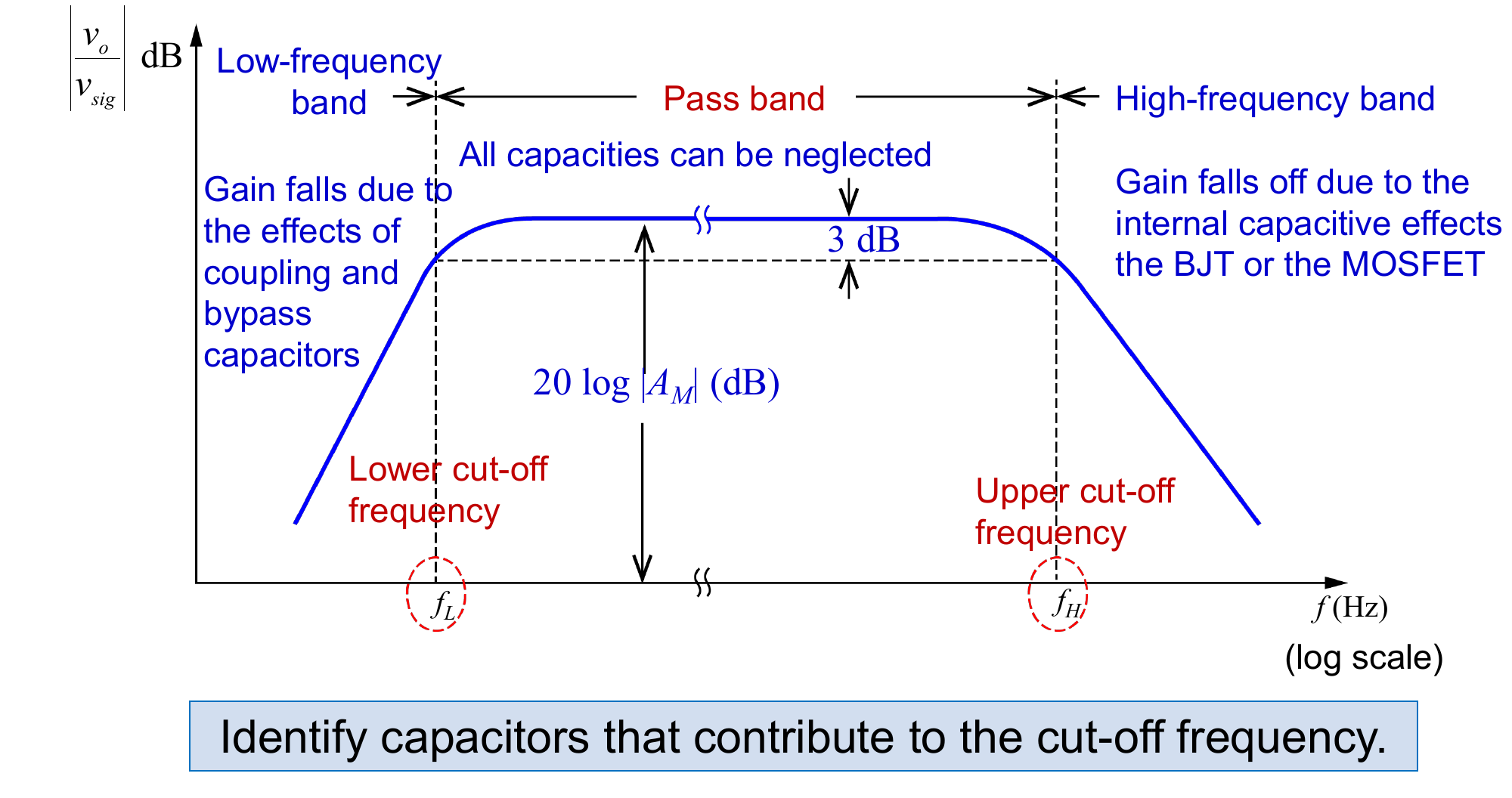
Bands:
- low-frequency band: gain falls because the coupling and bypass capacitors are no longer shorts (high-pass behaviour)
- pass band (mid-band): all capacitances can be neglected, gain from the small-signal analysis
- high-frequency band: gain falls because of the internal capacitances of the BJT or MOSFET (low-pass behaviour)
- the edges are the lower cut-off and the upper cut-off , both 3 dB below , and
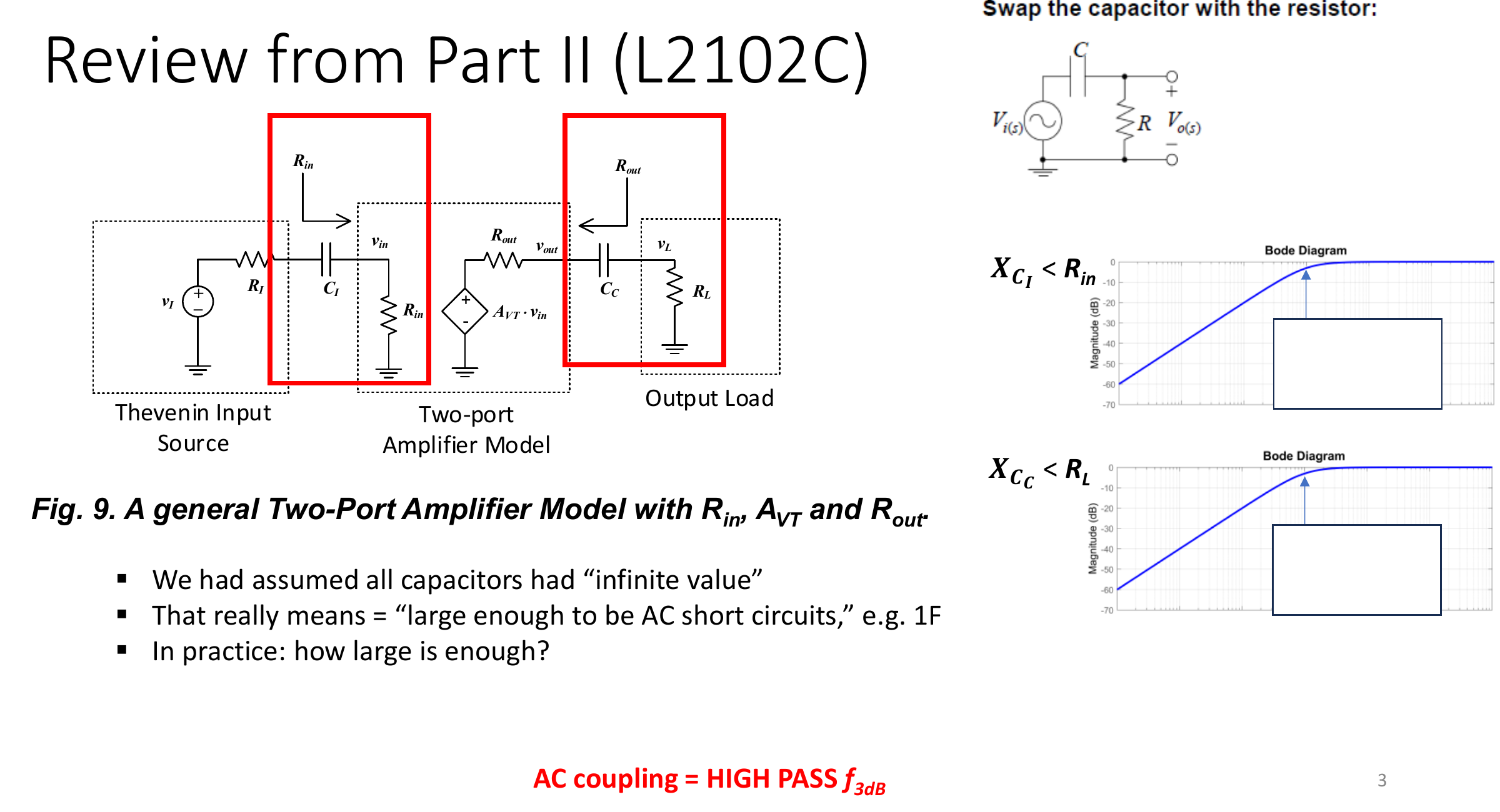
Coupling Capacitors in the Two-Port Model
Using the two-port model (source , amplifier , , , load ), each coupling capacitor forms a high-pass section with the resistance around it:
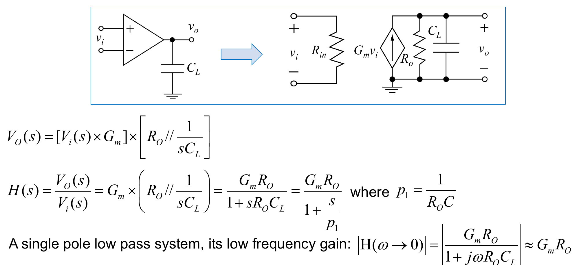
Single Stage With a Load Capacitor
Model the stage as with output resistance driving :
Results:
- low-frequency gain
- single pole low-pass, dB at
- unity-gain frequency where : , the gain-bandwidth product again
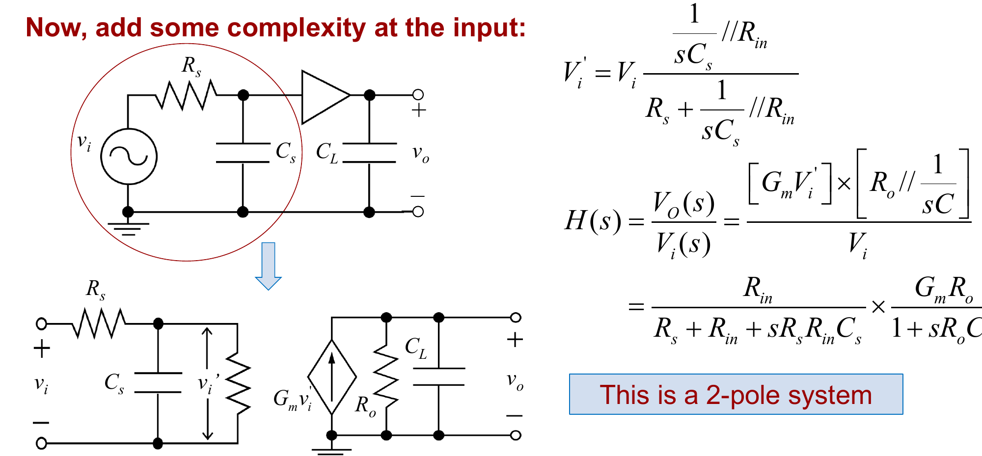
Adding an Input Capacitor
A source resistance with a capacitance at the input adds a second low-pass section:
Each pole is with the resistance seen by that capacitor.
Why Estimate
For a multistage amplifier with many capacitors, deriving the full by hand is impractical. Usually only and matter, and they can be estimated from time constants using the OCTC and SCTC Methods.