Source
Adapted from my own handwritten and hand-typed notes from Year 1 to Year 3 of my EEE degree
One resistor and one capacitor give the two basic first-order responses. Every coupling capacitor and every parasitic capacitor in an amplifier behaves like one of these.
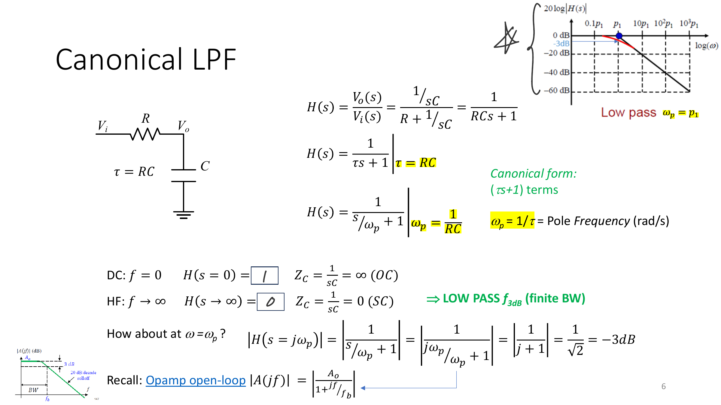
Canonical Low-Pass Filter
Series , shunt , output across :
Behaviour:
- DC: (open),
- high frequency: (short),
- at : , which is dB
- this is a finite bandwidth, the same shape as the op-amp open-loop gain
Canonical High-Pass Filter
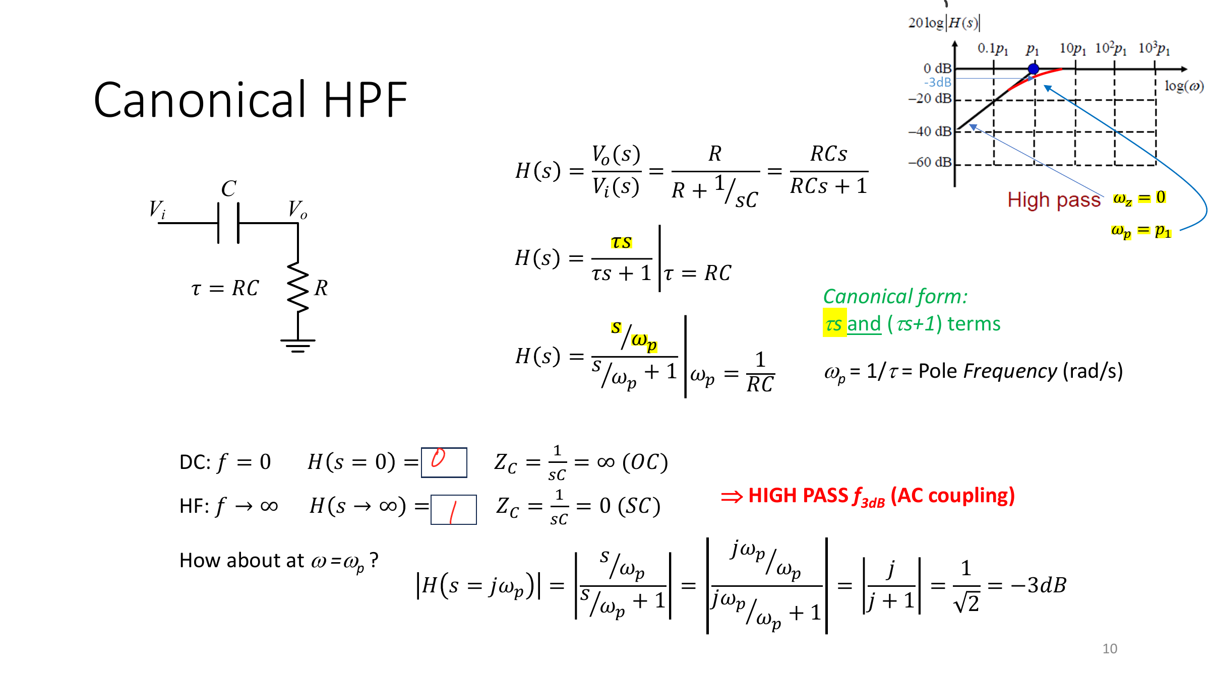
Series , shunt , output across :
Behaviour:
- a zero at the origin and a pole at
- DC: , high frequency: , dB at
- this is exactly what an AC coupling capacitor does
Sizing a Coupling Capacitor
Treating a coupling capacitor as a short only works if is small compared with the resistance it drives. With the capacitor feeding the corner is
which must sit below the lowest signal frequency. For kΩ and a lowest frequency of 20 Hz, µF.
Pole-Zero Pair
Series followed by a shunt branch of in series with :
This has a zero at and a pole at the lower frequency , so the gain steps down from 1 to (a lag network).
Active Filters
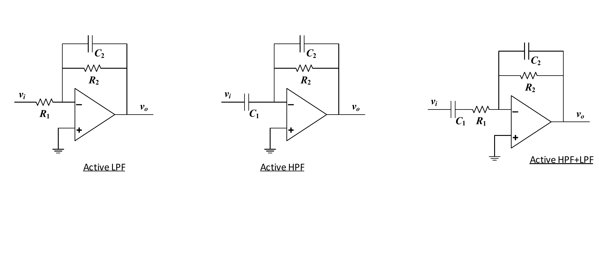
With an op-amp in the inverting configuration, , so the filter also has gain:
- , : active low-pass,
- , : high-pass behaviour from ,
- , : band-pass,
In an amplifier, high-pass sections set the low cut-off and low-pass sections set the high cut-off, see Amplifier Cut-off Frequencies.