Source
Adapted from my own handwritten and hand-typed notes from Year 1 to Year 3 of my EEE degree
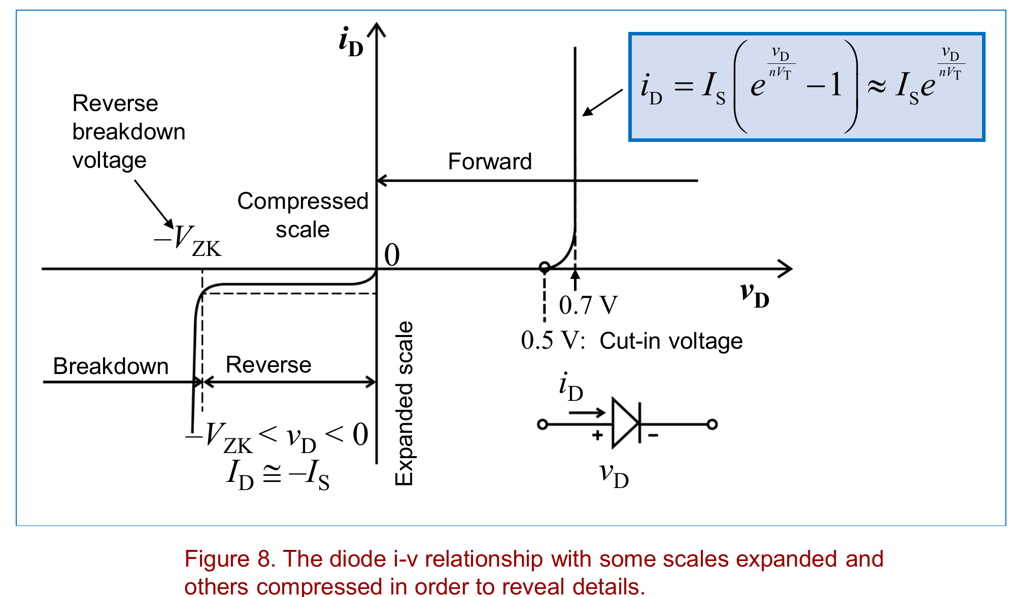
A real diode is a pn junction: p-type material next to n-type. Diffusion across the junction leaves a depletion region of fixed ions and a barrier potential, about 0.6 to 0.7 V for silicon and 0.2 to 0.3 V for germanium.
Biasing:
- forward bias: p side made more positive than n side, the depletion region narrows and current flows
- reverse bias: p side made more negative, the depletion region widens and the current is almost zero
Shockley Diode Equation
Terms:
- is the saturation current, about A for a small diode, and it doubles for every 10 °C rise
- is the emission coefficient, taken as 1
- is the thermal voltage, about 25 to 26 mV at 27 °C
Inverting for the voltage:
With , every decade of current only adds mV. For example a diode with 0.65 V at 1 mA has about 0.83 V at 1 A. The simple model just uses V whenever the diode conducts.
Three Regions
| Region | Condition | Behaviour |
|---|---|---|
| Forward | Shockley equation, negligible current below the 0.5 V cut-in, 0.5 to 0.9 V when conducting | |
| Reverse | once | |
| Breakdown | large reverse current at the breakdown voltage |
Temperature Effect
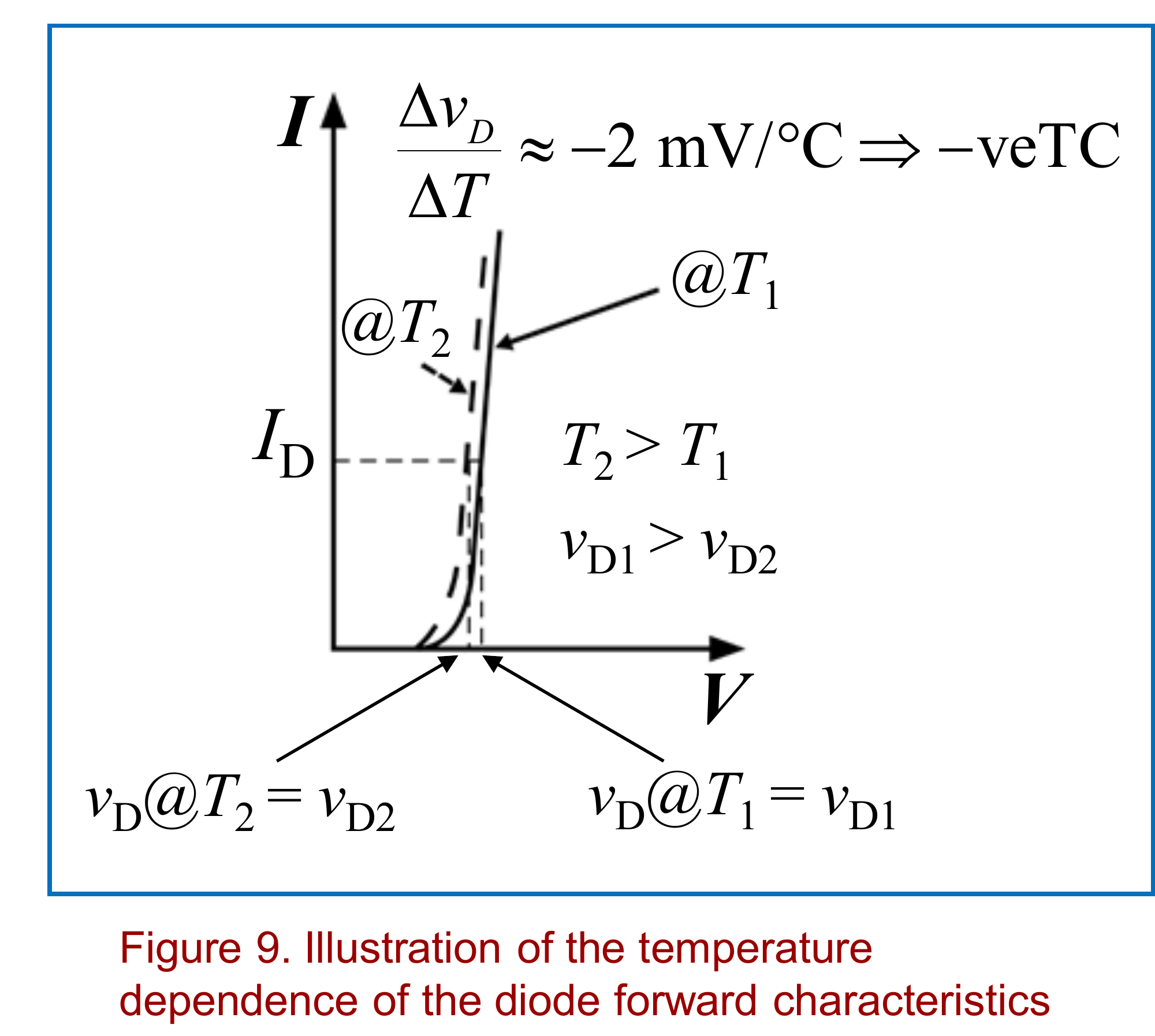
At a fixed current, drops by about 2 mV per °C. This negative temperature coefficient can be used as a thermometer.
Finding the actual operating point in a circuit is covered in Diode Q-Point Analysis.