Source
Adapted from my own handwritten and hand-typed notes from Year 1 to Year 3 of my EEE degree
Procedure
Analysis steps:
- identify the functional blocks: flip-flops, next-state decoder and output decoder
- write the Boolean expressions for every flip-flop input and every output
- plot these on K-maps (state maps)
- build the present state / next state table using the flip-flop characteristic tables
- draw the state diagram from the table
- describe what the circuit does
Example With SR Flip-Flops
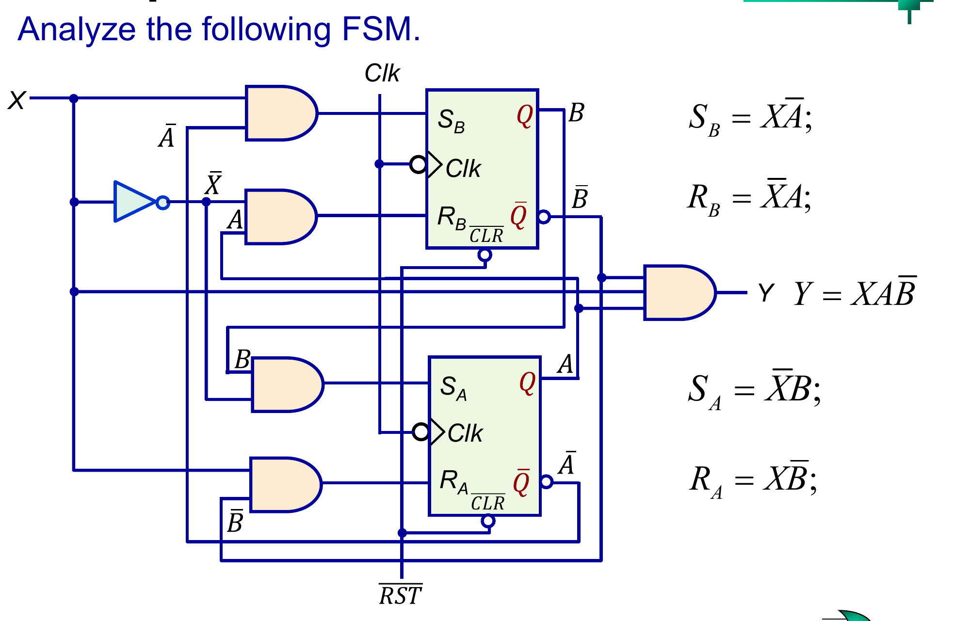
Equations read from the circuit (state , input ):
Present / next state table:
| 00 | 0 | 00 | 00 | 0 | 00 |
| 00 | 1 | 01 | 10 | 0 | 01 |
| 01 | 0 | 10 | 00 | 0 | 11 |
| 01 | 1 | 00 | 10 | 0 | 01 |
| 10 | 0 | 00 | 01 | 0 | 10 |
| 10 | 1 | 01 | 00 | 1 | 00 |
| 11 | 0 | 10 | 01 | 0 | 10 |
| 11 | 1 | 00 | 00 | 0 | 11 |
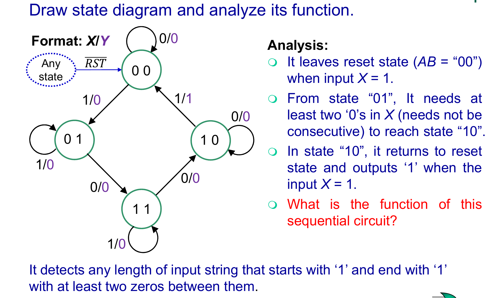
Behaviour:
- it leaves the reset state 00 when
- from 01 it needs at least two 0s (not necessarily consecutive) to reach 10
- in 10 an input of 1 outputs and returns to 00
So it detects any input string that starts with 1 and ends with 1 with at least two 0s in between.
Unused and Hold States
With flip-flops there are codes. Some may never be reached in normal operation (unused states); the circuit only enters them through noise or at power on.
Things to check:
- a hold state is an unused state that traps the machine (it never leaves), which must be avoided in a design
- an unused state that returns to the main sequence within a clock or two is harmless
- a reset input that forces a known state is the usual protection
Example: a 3-bit twisted ring counter with , , cycles through 000, 100, 110, 111, 011, 001. The two other codes, 010 and 101, form an isolated loop that swaps between them forever, which is typical of twisted ring counters without self-correction.
A programmable hold state is a deliberate hold state entered with a specific input and released only by a special reserved input. It can be useful as a debugging feature.