Source
Adapted from my own handwritten and hand-typed notes from Year 1 to Year 3 of my EEE degree
Sequential Circuit Model
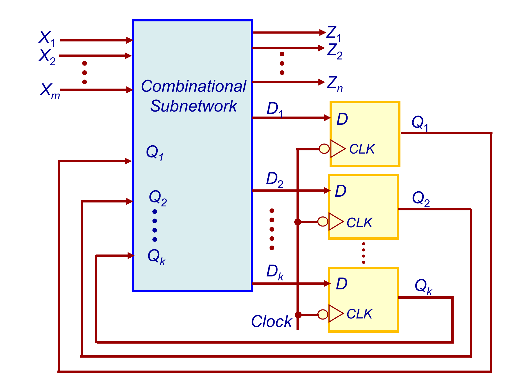
A finite state machine (FSM) has a finite number of states, only one active at a time, and moves between them in response to inputs. It is built from combinational logic plus memory, with feedback from the memory to the logic.
With inputs , outputs , present state and next state (excitation) :
Two kinds of sequential circuit:
- synchronous: all state changes happen together, controlled by a clock, with flip-flops as memory
- asynchronous: no clock, the state can change whenever the inputs change, often just combinational logic with feedback
Mealy Machine
In a Mealy machine the outputs depend on both the inputs and the present state.
In the state diagram each arrow is labelled X/Z: the input that causes the transition and the output produced in the present state for that input.
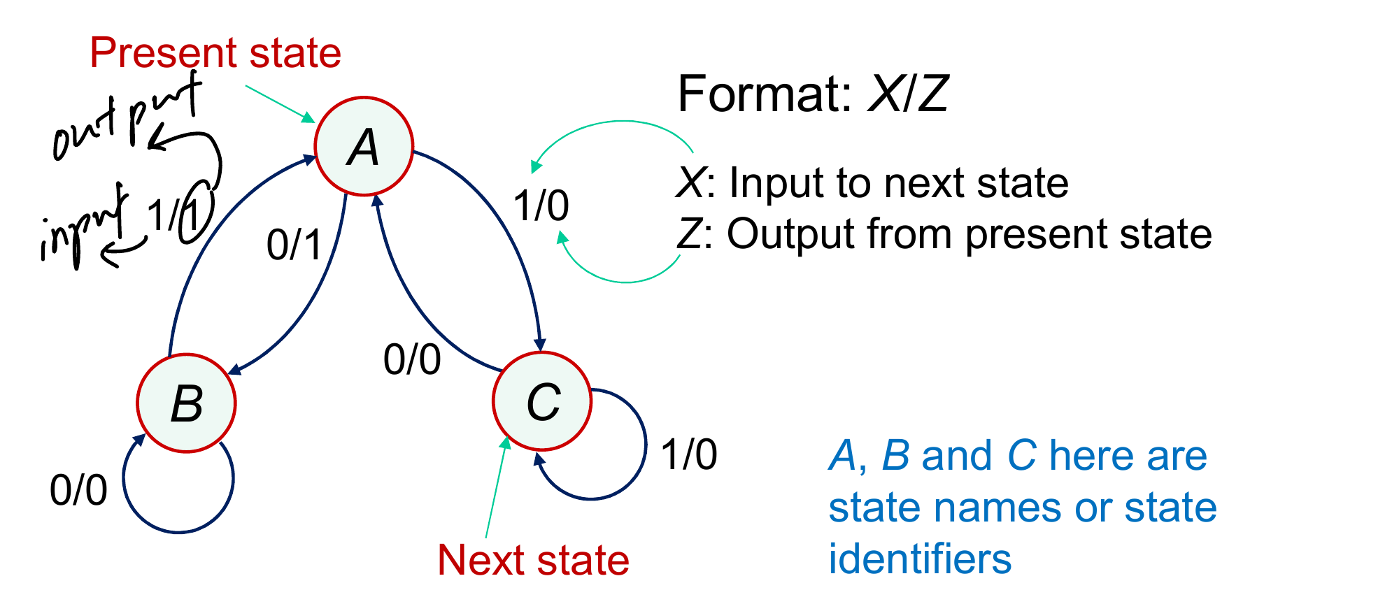
State table for this diagram (entries are next state, output):
| Present | ||
|---|---|---|
| A | B, 1 | C, 0 |
| B | B, 0 | A, 1 |
| C | A, 0 | C, 0 |
Example: starting in A with , the states go A B A C A C A C C A B, giving and a final state B.
Since depends directly on , a Mealy output can change whenever the input changes, even between clock edges. If changes asynchronously this causes spurious output pulses, so a Mealy output should be sampled only after the circuit has settled following an input change.
Moore Machine
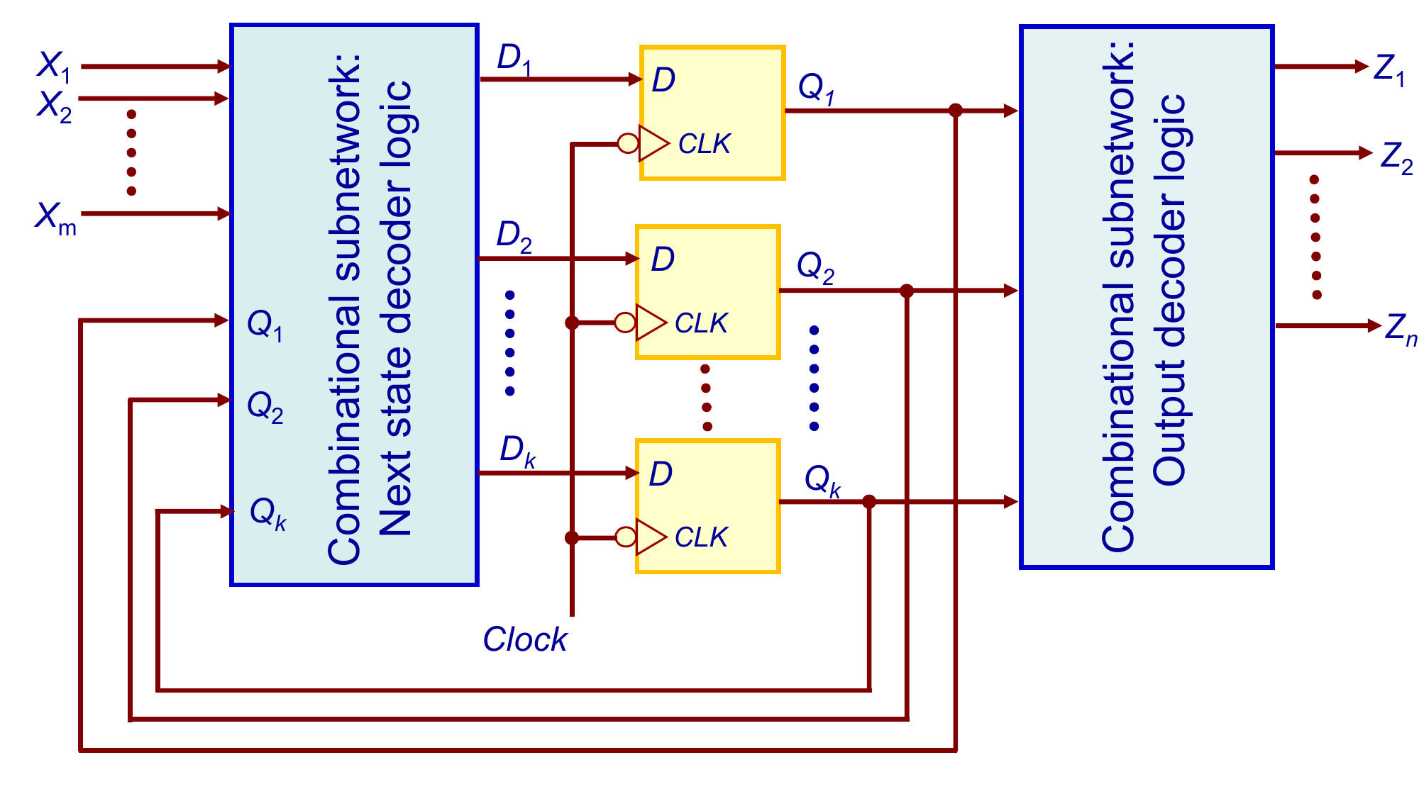
In a Moore machine the outputs depend only on the present state. The combinational logic splits into a next-state decoder and an output decoder.
The output is written inside each state circle and arrows carry only the input value.
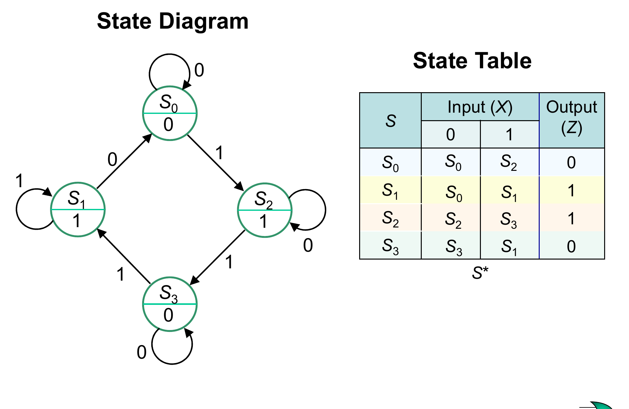
Since the output comes from the flip-flops only, it changes only when the state changes on a clock edge. An input change with no state change has no effect on the output, so Moore outputs are glitch free but usually one clock later than the equivalent Mealy output.
Comparison
| Mealy | Moore | |
|---|---|---|
| Output depends on | inputs and state | state only |
| Output shown | on arrows (X/Z) | in states |
| Output timing | can change any time the input changes | changes only on clock edges |
| Number of states | often fewer | often more |
How to work backwards from a circuit to its diagram is in FSM Analysis.