Source
Adapted from my own handwritten and hand-typed notes from Year 1 to Year 3 of my EEE degree
One-Port Networks
A port is a pair of terminals where the current entering one terminal equals the current leaving the other. This is the port condition. A one-port has a single such pair, for example a resistor, capacitor or inductor, or any network seen from two terminals. Only the port relation between and matters, which is the driving point impedance .
Two-Port Networks
A two-port network is a linear network with two pairs of terminals: an input port (1) and an output port (2). Examples are amplifiers, filters, transformers, transmission lines, transistor models and T or resistor networks.
Two-Port Block Diagram
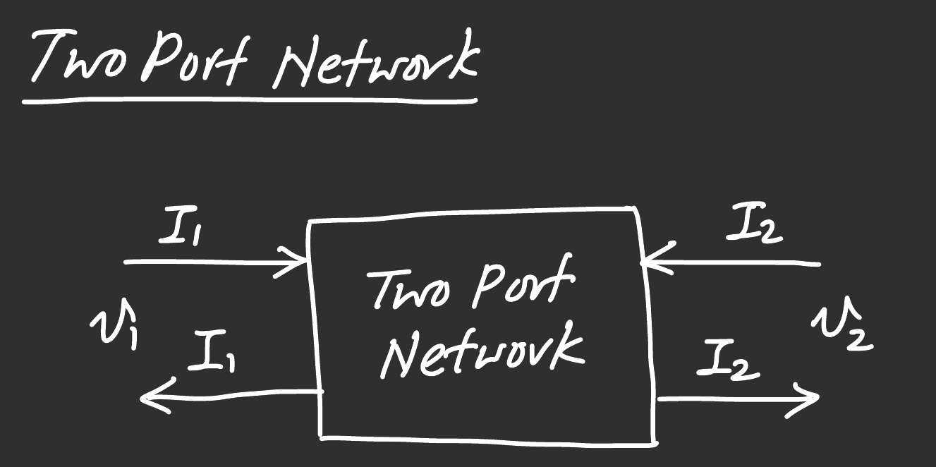
Standard reference directions:
- and both flow into the network at the top terminals
- and are positive at the top terminals
Why Use Two-Port Parameters
The network can be treated as a black box. Two simple experiments give four numbers (the two-port parameters), and these predict what happens when any source is put on one port and any load on the other, without knowing what is inside.
Assumptions:
- the network is linear
- there are no independent sources inside
- all initial conditions are zero
Four Parameter Sets
Of the four port variables , any two can be written in terms of the other two:
| Parameters | Unknowns written as | In terms of | Main use |
|---|---|---|---|
| Impedance | series connections | ||
| Admittance | parallel connections, ladder filters | ||
| Hybrid | transistor models | ||
| Transmission | cascaded networks, transmission lines |
The first set is the Impedance Parameters.