Source
Adapted from my own handwritten and hand-typed notes from Year 1 to Year 3 of my EEE degree
The step response is the behaviour of a circuit when a DC source is suddenly switched on, modelled with the unit step function.
Unit Step Function
A voltage source is equivalent to a source behind a switch that closes at .
RC Step Response
With and a source , KCL gives
whose solution for is
Natural Plus Forced Step Response
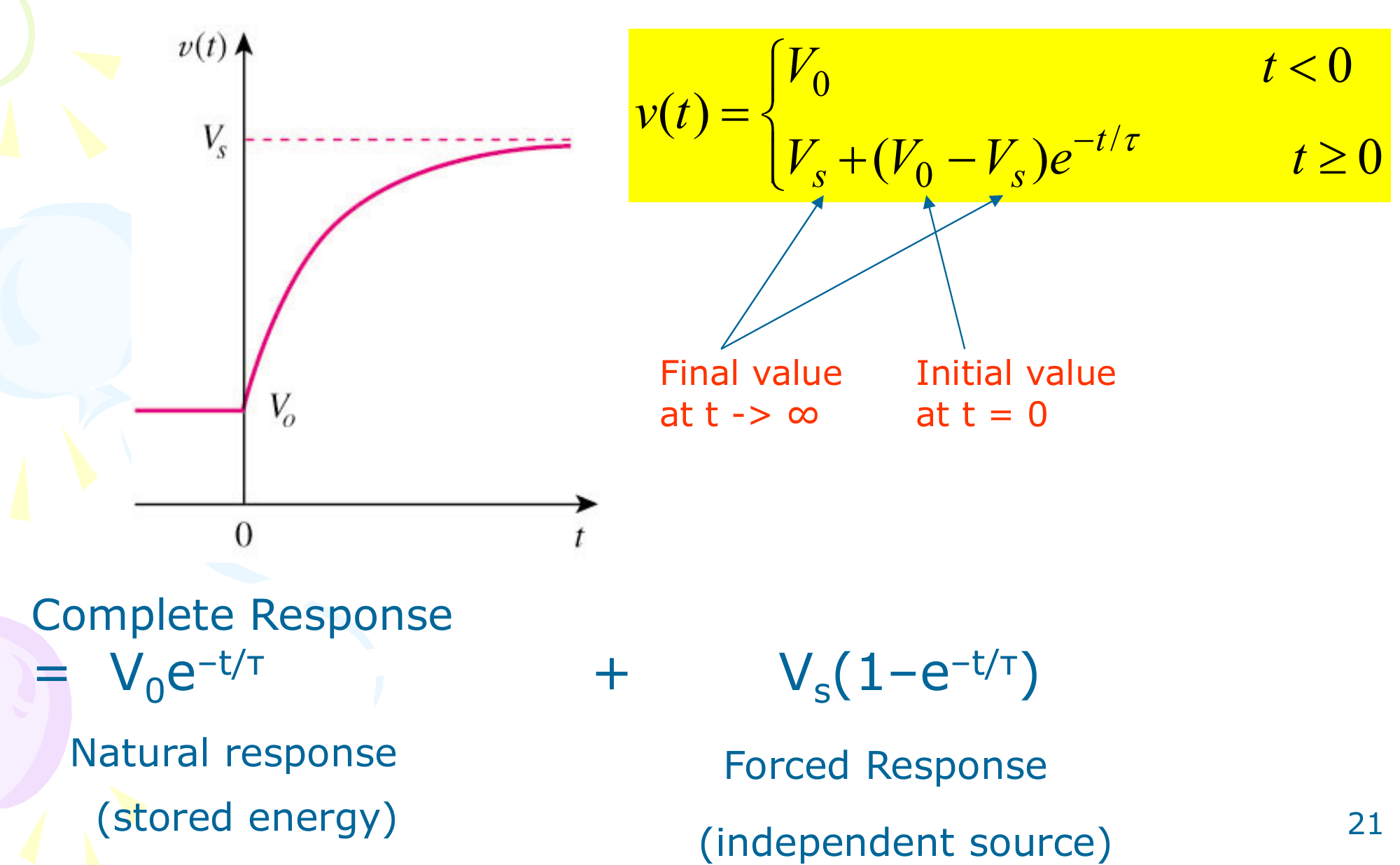
This splits two ways:
- natural + forced: (from stored energy) plus (from the source)
- transient + steady state: dies out, remains
General Three-Step Method
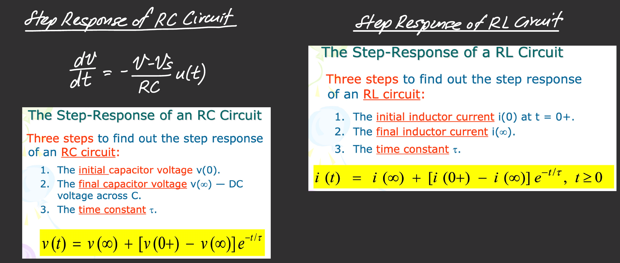
For any first-order circuit, choose the capacitor voltage (RC) or inductor current (RL) and find:
- The initial value at
- The final value as (DC steady state)
- The time constant or
Then
where is the switching time (usually 0).
RC Example
A current source A feeds 6 in parallel with a branch of 2 and 0.25 F, with :
- s
- V (capacitor open, all current in 6 )
- V
RL Example
A 20 V source with 1 and 3 in series feeds an 80 mH inductor. The switch closes at and shorts the 3 :
- A (inductor was a short)
- A
- s
- A for
For circuits with more than one storage element, the cleaner tool is s-Domain Circuit Analysis.