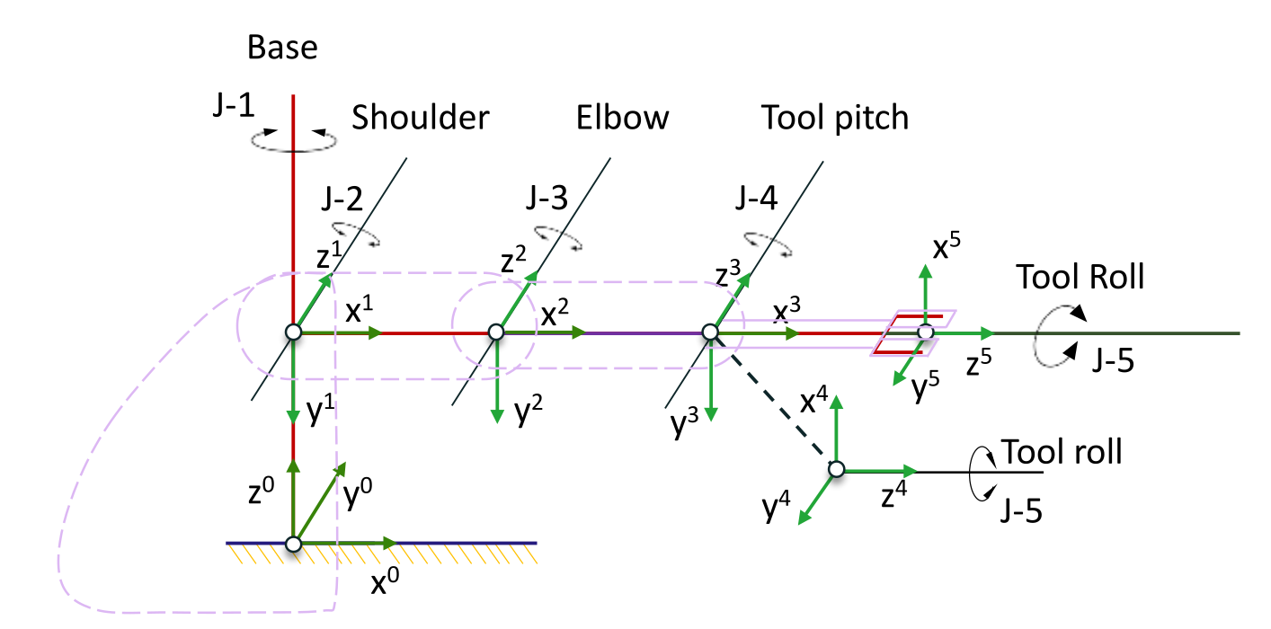
All explanation will be for this Alpha II robotic arm
We split this up into two-pass procedure:
Phase I (Steps 0 - 7):
we will physically walk along the robot arm from the floor to the gripper, sticking coordinate axis "stickers" () on each link.
Part II (Steps 8 - 13):
we go back to the beginnning of the robot (base) and measure the exact physical distances and twist the angles between those stickers to fill out our D-H Parameter Table.
Phase I
Step 0: Number the joints
Before placing axis (stickers), we need to count the number of individual Yaw, Pitch and Roll joints seperately. Number them from 1 to , starting from the joint closest to the floor (the base joint) and ending at the final tool position.
Joints are counted from 1 onwards, so joint 1, joint 2, etc.
Step 1: Set up the Base Frame ()
Place our first coordinate sticker () at the fixed base of the robot. In D-H, the Z-axes are always joint axes. The joint axes is the physical line in 3-dimensional space about or along which relative motion between 2 connected links occurs. So let's say a particular link rotates about a certain axis, this axis is .
Links and Coordinate Frames are counted from 0 onwards.
Therefore,
- If motion is linear (Prismatic Joint), we point directly along the line of motion
- If motion is rotational (Revolute Joint), is the axis that the link rotates about
Once is set, we can place and axes in any way we want. Since is the starting point of the entire robot, there are no previous axes or joints to constrain it. However, there are 2 strict rules and 1 convention to follow. Rule 1 is that all 3 axes must be perpendicular to each other, and that and are in the same plane with pointing out of that plane. Rule 2 is that . Using right-hand rule, index finger in direction of , middle finger in direction of , and thumb in .
Step 2: Align the next Z-axis ()
Now we look at the next joint in the chain, which is joint 2 (Shoulder). Because joint 2 is the shoulder hinge that tilts the arm up/down, its rotational axis is horizontal. Therefore, we must point out horizontally sideways, sticking out of the robot's shoulders.
Step 3: Locate the center (origin) of Frame
For this step we need to look at the new (sideway shoulder axis) and the previous (vertical waist axis). We need to check if they intersect. They do intersect, where they cross at a point inside the shoulder's housing. We can therefore place the origin of Frame exactly at this crossing point.
Step 4: Place
- ok simple rule to follow: lies along the common normal between and , pointing from towards
- one very important point is that if and are parallel to each other, means we need to pick a point anywhere along this particular parallel plane from towards
Step 5: Place
Form the right-hand rule.
Phase II
Now we can fill up the physical relationship between our frames and fill out the D-H Table.
where:
- Axis refers to the joint or link number in the robotics chain, joint connects link to .
- refers to the joint angle, or the angle of rotation about the previous z-axis. The physical meaning of this is "how much we gotta rotate around the previous X-axis so that it points parallel to the current X-axis "
- is the distance of translation along the previous Z-axis. It measures how far we must slide along the joint axis to get to the previous X-axis () to physically interact with the current X-axis ()
- measures the physical length of the rigid link. It is the distance along the common perpendicular bridge () required to make joint axis physically intersect with joint axis
- measures the structural twist of the link. It is the angle we must rotate around to tilt the previous joint axis so that it aligns parallel with the current joint axis
1 PAGE SUMMARY OF DH
- place in the same line as joint axes
- start with at first joint,
- always lie along the common normal between and , pointing from towards
- one very important point is that if and are parallel to each other, means we need to pick a point anywhere along this particular parallel plane from towards
where:
- , and origin at
- we view from top view, such that points out of the page, in this view anti-clockwise is positive
Intuitive way of thinking about which comes first:
Looking at , it is the transformation matrix to transform coordinate frame base to wrist. In otherwords, the wrist coordinate frame with respect to base coordinate frame. We add first and then post-multiply after, because once we add , we are already in the coordinate frame , and we are performing the transform with respect to its current coordinate frame , no longer the base coordinate frame .