Source
Adapted from my own handwritten and hand-typed notes from Year 1 to Year 3 of my EEE degree
The same four-resistor layout (, , , ) biases a MOSFET. It is simpler than the BJT case because no gate current flows, so the Thevenin resistance carries no voltage drop.
Method
Assume saturation. With , KVL around the gate-source loop gives a quadratic in :
Then:
- keep the root with
- check
Worked Example
V, MΩ, MΩ, kΩ, kΩ, µA/V², V.
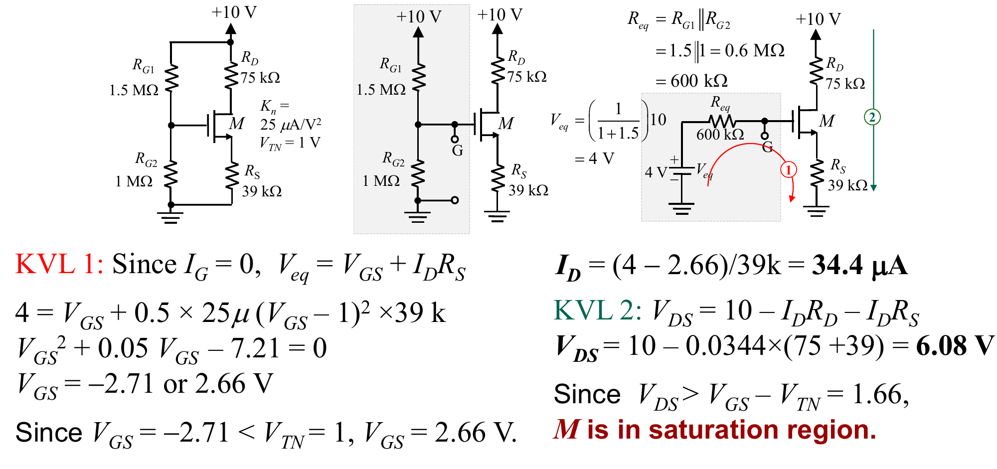
Steps:
- V, kΩ (does not matter, no current)
- , which simplifies to
- roots V (below , rejected) and V
- µA
- V
Since V, the MOSFET is in saturation as assumed. These Q-point values feed the MOSFET Small-Signal Model.