Source
Adapted from my own handwritten and hand-typed notes from Year 1 to Year 3 of my EEE degree
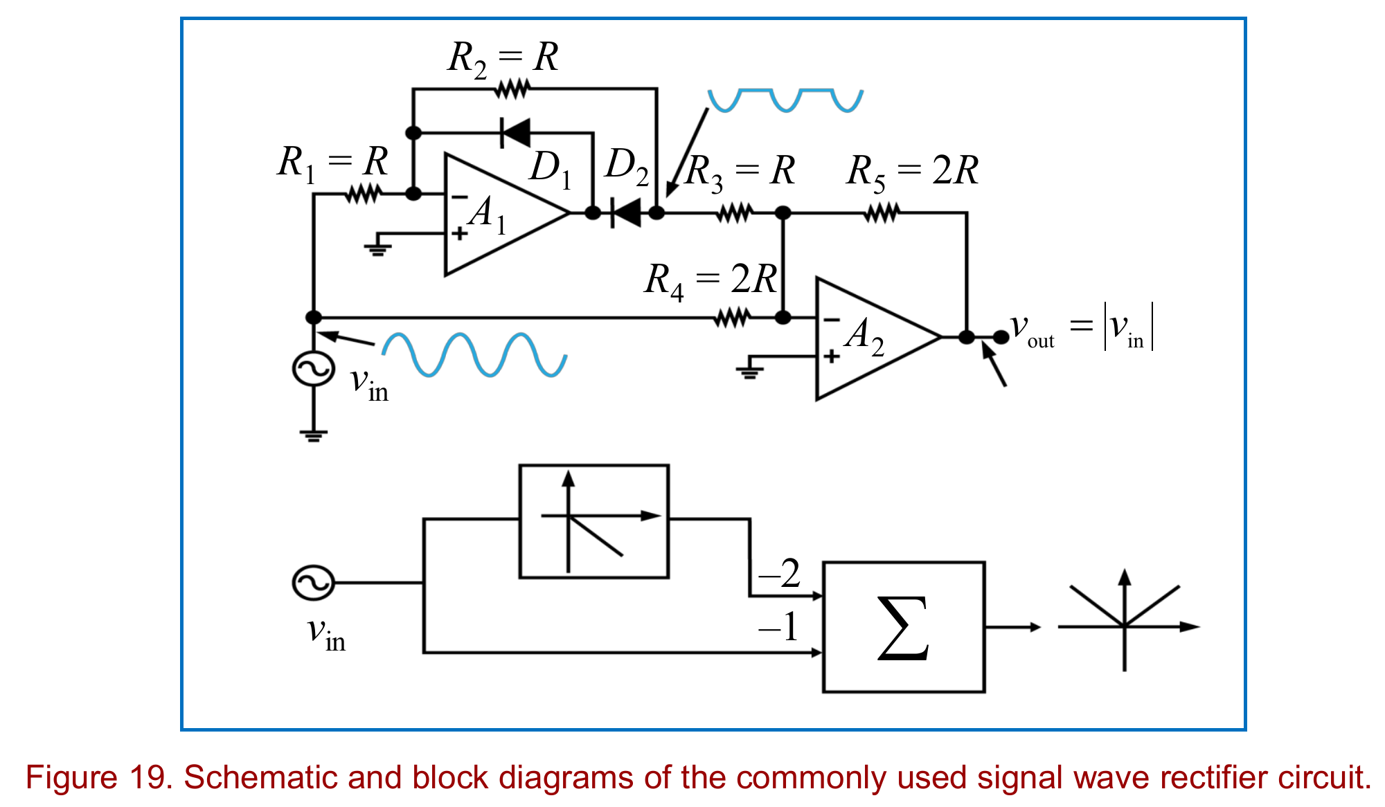
A precision full-wave rectifier built from two op-amps and two diodes. Its output is , with no diode drop, so it also works for signals much smaller than 0.7 V.
Absolute Value Circuit
Structure
Blocks:
- with and diodes , is a precision half-wave rectifier with gain
- is an inverting summer with feedback
- the half-wave output reaches through (weight )
- the raw input reaches through (weight )
So where is the rectified signal.
Positive Input
Operation:
- output goes negative, so is reverse biased
- conducts and closes the loop through , so is an inverting amplifier and
Negative Input
Operation:
- is forward biased and closes the loop around directly
- is off, so the rectified node sits at virtual ground,
- only inverts the input, , which is positive
Both cases give a positive output equal in size to the input. The diode drops are inside the feedback loop of , so the op-amp gain hides them. Compare the plain diode version in Rectifiers and DC Power Supplies.