Source
Adapted from my own handwritten and hand-typed notes from Year 1 to Year 3 of my EEE degree
Counters
A counter is a clocked sequential circuit that steps through a fixed sequence of states. A counter with states is a modulo-m (divide-by-m) counter. An n-bit binary counter counts and then wraps to 0.
Ways to classify counters:
- clocking: synchronous or asynchronous
- sequence type (binary, BCD, Gray, ring)
- modulus (number of states)
- number of flip-flops
Uses include timing units, control circuits and signal generators.
In a synchronous counter every flip-flop shares the same clock, so all outputs change together.
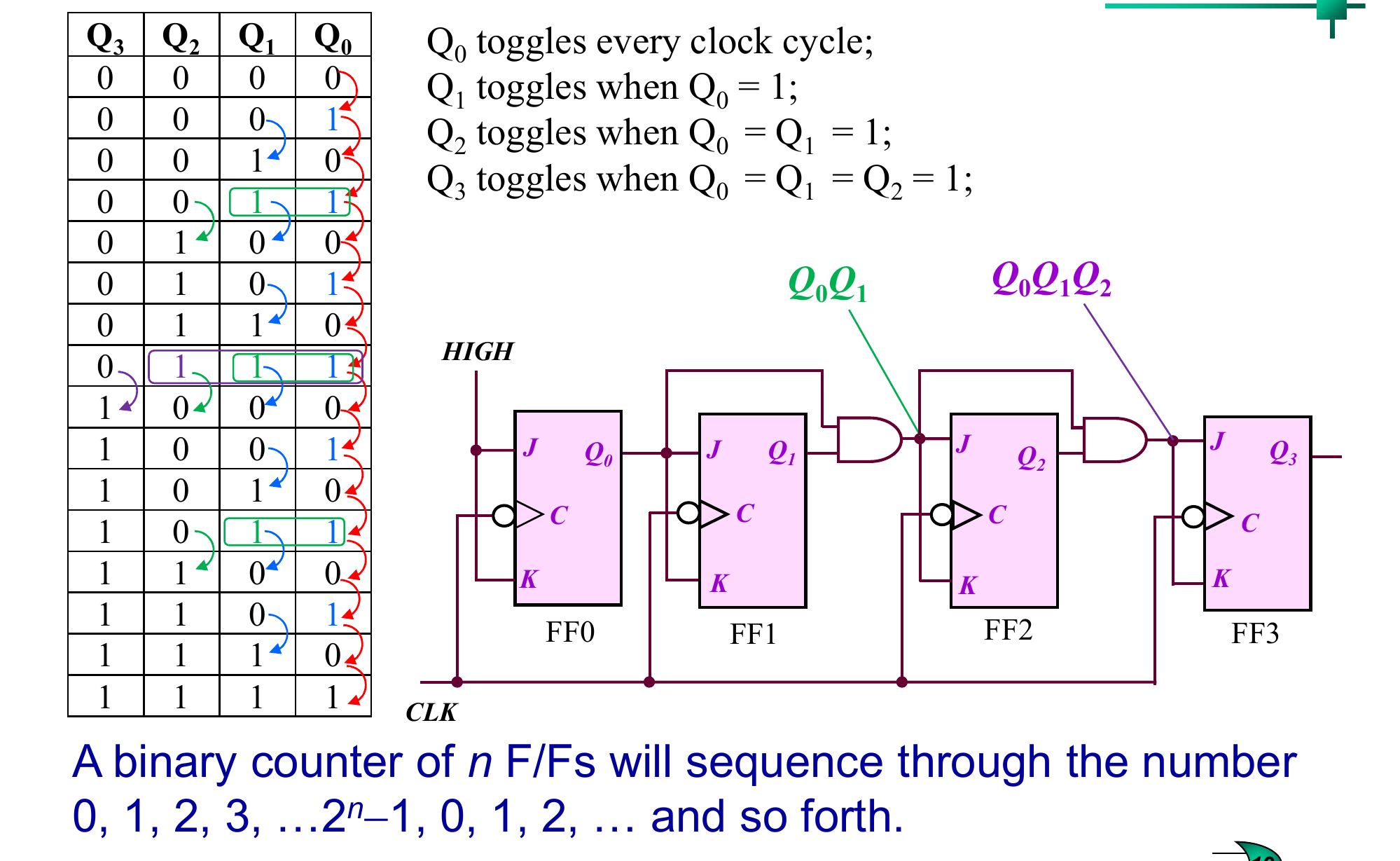
4-Bit Synchronous Binary Counter
Looking at the binary count sequence:
- toggles every clock
- toggles when
- toggles when
- toggles when
So with JK flip-flops in toggle mode ():
Control Circuitry
Common additions:
- count inhibit: AND an enable into (and the chain) to hold the count
- clear: drive all the inputs to reset the counter
- ripple carry out (RCO): goes high at the final count and enables the next counter module when cascading
Up/Down Counter
For counting up, each flip-flop toggles when all lower outputs are 1. For counting down, it toggles when all lower outputs are 1. An UP/DOWN line selects which set drives the J and K inputs through AND-OR gates.
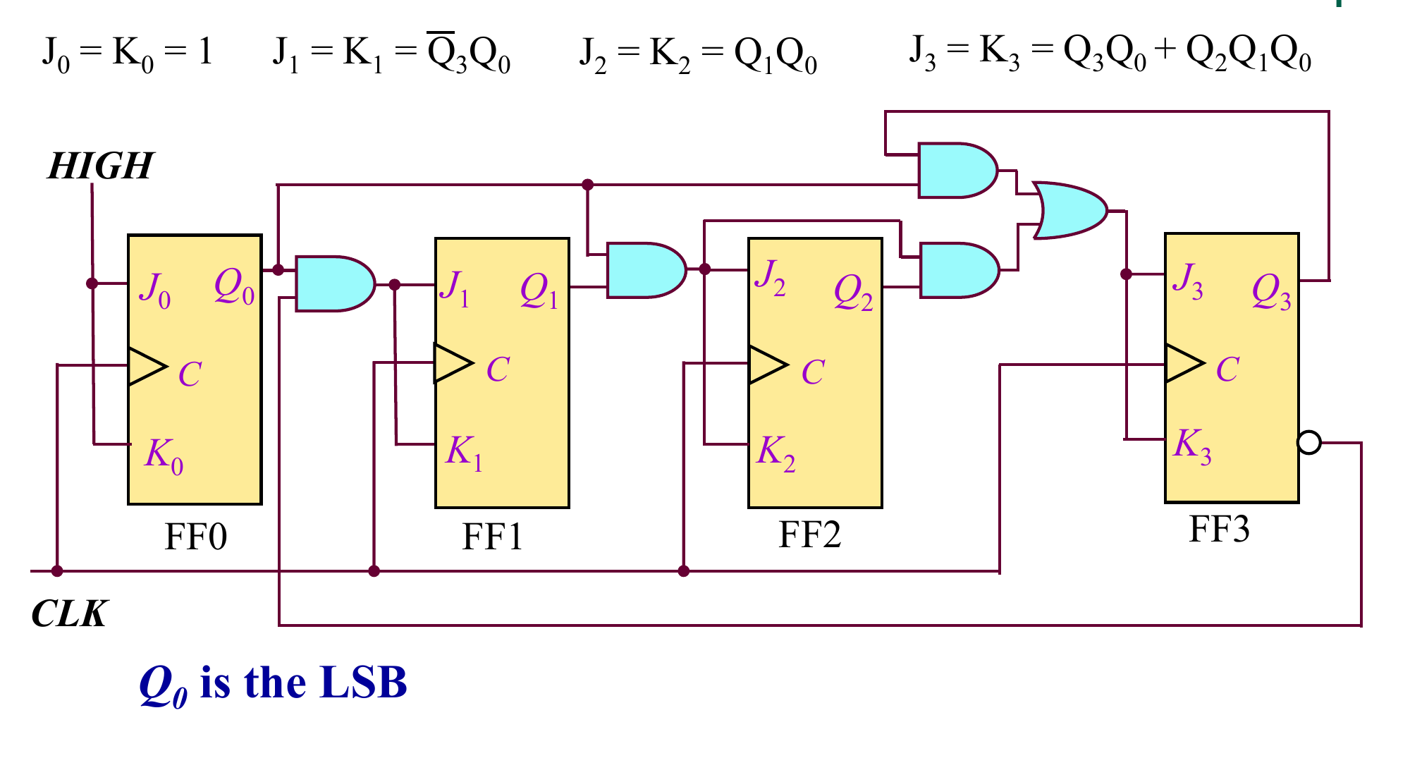
Synchronous BCD Decade Counter
Counts 0 to 9 then back to 0. Using T flip-flops (JK with ) and treating codes 10 to 15 as don't-cares in the K-maps:
The in stops toggling at 9 (1001), so the next state is 0000 instead of 1010.
MSI Counters
74LS160 (4-bit synchronous BCD counter):
- is an asynchronous clear
- loads to synchronously on the next clock
- counting needs both ENP and ENT high, either low inhibits (hold)
- is high at count 9, used for cascading
74LS190 (synchronous up/down decade counter) has an active-low count enable , a direction input, asynchronous load, and MAX/MIN and RCO outputs.
Counters with no common clock are covered in Asynchronous Counters.