Source
Adapted from my own handwritten and hand-typed notes from Year 1 to Year 3 of my EEE degree
An operational amplifier (op-amp) is an active element that behaves like a voltage-controlled voltage source. It is used for amplification, active filters, oscillators, comparators and regulators. In this module only its terminal behaviour matters, not its internal transistors.
Terminals
A typical 8-pin DIP op-amp (such as the 741) has five terminals that matter:
- inverting input (), pin 2
- non-inverting input (), pin 3
- output, pin 6
- positive supply , pin 7
- negative supply , pin 4
A signal at the non-inverting input appears at the output with the same polarity, while a signal at the inverting input appears inverted. The output is limited by the supplies, (saturation).
Equivalent Circuit Model
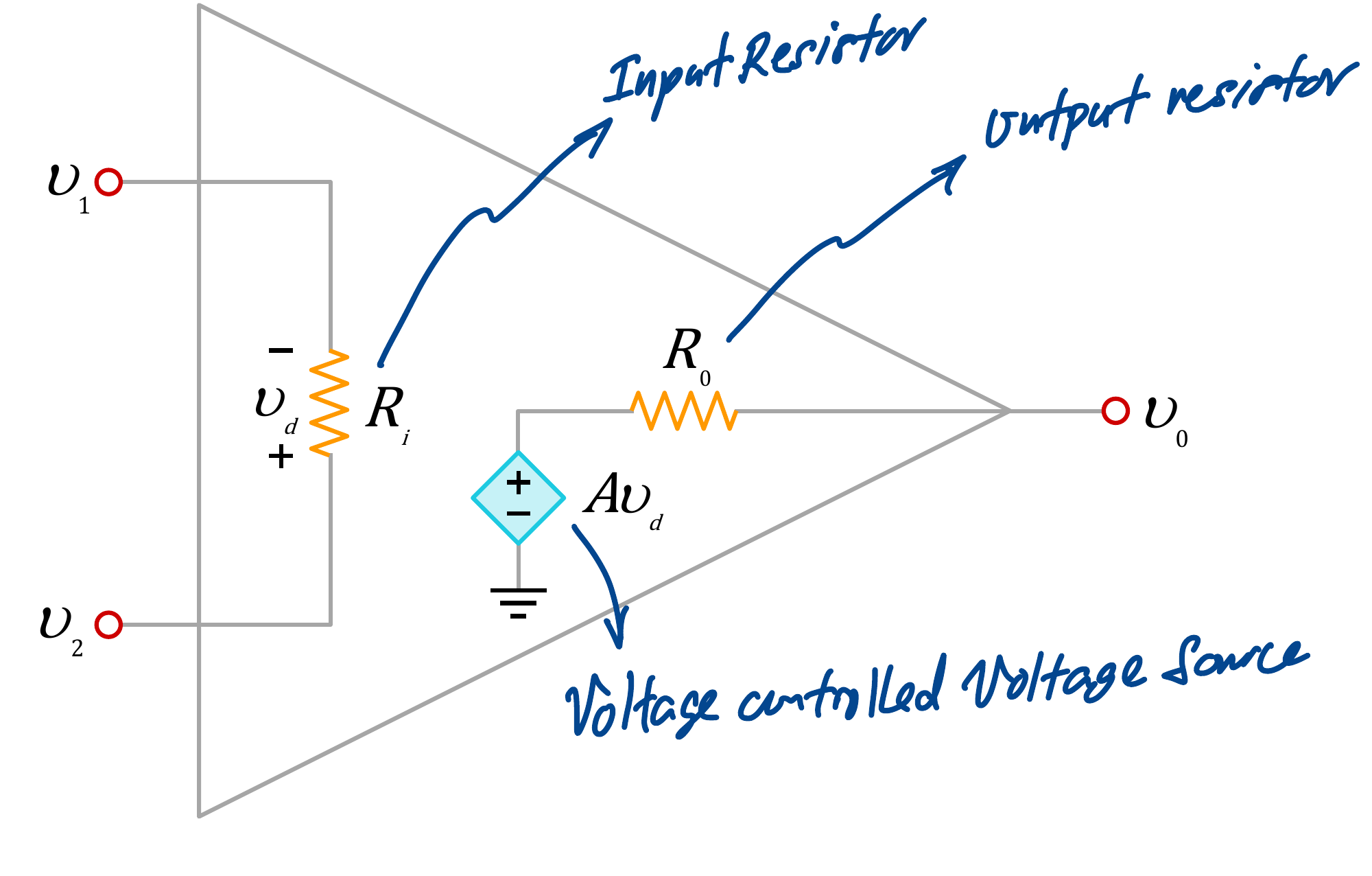
The real op-amp is modelled by an input resistance across the inputs, an output resistance and a VCVS , where is the differential input and is the open-loop gain (around or more).
Ideal Op-Amp
An ideal op-amp has:
- infinite open-loop gain,
- infinite input resistance,
- zero output resistance,
Because is so large, negative feedback (output fed back to the inverting input) is used to control the gain. The gain with feedback is the closed-loop gain.
Two golden rules
With negative feedback, an ideal op-amp has (no current into either input) and (no voltage between the inputs). Most op-amp problems are just these two rules plus nodal analysis.
The output current is not zero, since the op-amp draws it from the supplies.
Common Amplifiers
| Circuit | Closed-loop gain |
|---|---|
| Inverting ( through into , from output to , grounded) | |
| Non-inverting ( into , from to ground, from output to ) | |
| Voltage follower (, ) |
Worked Example
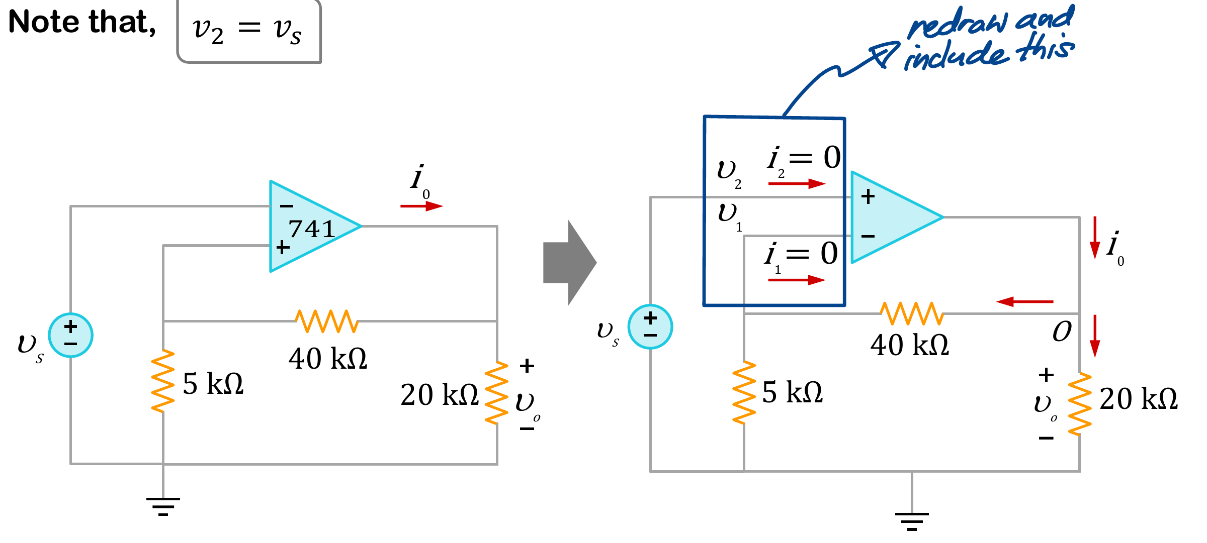
Find the closed-loop gain and when V:
- the non-inverting input is
- no current enters the inverting input, so 40 k and 5 k are in series and form a divider:
- ideal rule gives , the same as
- with V, V and KCL at the output node gives mA