Introduction
Given the pose of the end-effector, we can find the joint variables.
Joint Space
Joint Space is the list q = [q1, q2, q3, ... , qn]. This are the rotations about the joints axes.
Tool Configuration Space
This is where the tool tip is and which way it is facing. It has 6 dimensions, 3 for position and 3 for orientation.
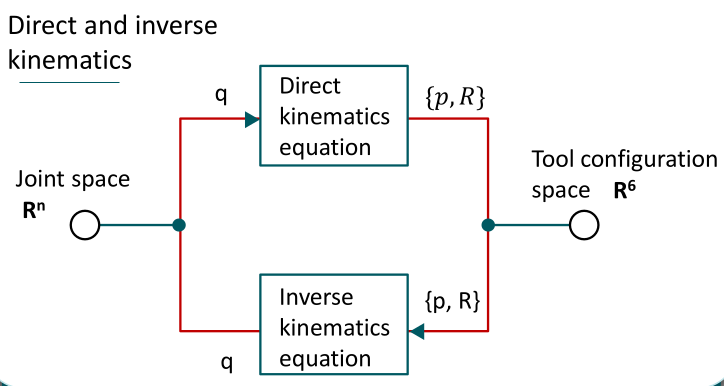
Forward (Direct) kinematics goes from q to {p, R} using D-H algorithm. But for Inverse Kinematics, we are trying to go from {p, R} back to q. This is harder since there is no systematic procedure like D-H.
Work Space
It is all the possible positions in the space that the robot arm can reach. So when we wanna check the existance of solution for an inverse kinematics problem, we would mean that the end effector's pose has to be within the work space.
General Properties of Solutions
Existence of Solutions
From the arm equation,
We can see that there are 16 entries, where the bottom row is just s and s which gives us no extra information. Therefore, removing that row, we are left with 12 entries.
Also, the 9 rotation numbers are not independent, because is a coordinate transformation matrix that obeys:
This condition supplies 6 restrictions:
For General Manipulation:
Uniqueness of Solutions
Having 6 axes is necessary, but it does not gaurantee a solution. The target must be in the work envelope, the joint limits must not be broken, and even then the answer may not have a closed-form formula.
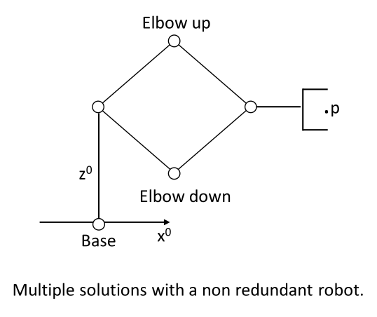
Typically the solutions for joint variables is usually not unique. Meaning there are multiple ways to achieve the same TCP pose.
Tool Configuration Vector
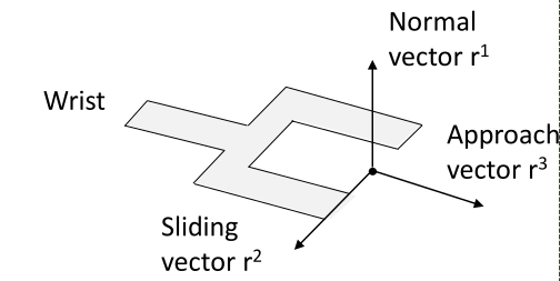
Problem: The issue is to ask the robot for a pose, we must hand it {p, R}, which is 12 numbers. However, only 6 of them are independent. We are giving twice as much data as needed. Position wise, we are not wasting anything since p has 3 numbers and 3 freedoms. However, for orientation, we just need to give 3 numbers, but R uses 9.
Solution: Therefore, we take only the third column of R, which is the approach vector , which is shown above. This fixes 2 of the 3 orientation freedoms, which are the yaw and pitch. The roll angle, which is angle of rotation about approach vector will still be an unknown.
r3 is a unit vector, so its length is always 1 and carries no information. We can scale the vector so that the length is:
Let and denote the position and orientation of the tool frame relative to base frame where represents the tool roll angle. Then the tool configuration vector in defined:
Tool Configuration of a Five-Axis Articulated Robot
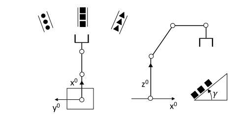
A five-axis robot has n=5, so by the rule above, it cannot reach arbitrary poses. This section finds exactly which poses it loses.
Joint 1 rotates the whole arm about the vertical base axis. Every joint after that rotates about a horizontal axis. So joints 2 to 5 move the arm inside one vertical plane, and that plane always contains the base axis. Joint 1 only chooses which vertical plane.
Therefore, both the tool position and the approach vector are trapped in that same vertical plane that Joint 1 'selected'. Seen from above, this vertical plane collapses to a line through the origin. Seen from the side view (that plane's view), the horizontal part of and the horizontal part of point along the same direction, as shown below.
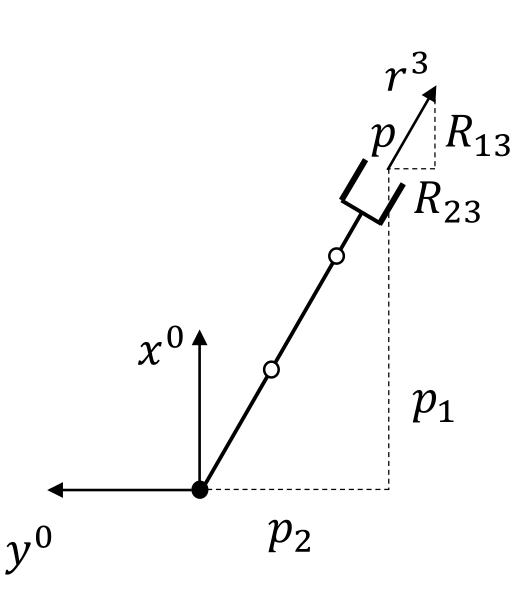
This equation just compares the two horizontal directions using similar triangles, where:
- is the x-component of the approach vector, which is the direction the tool points
- is the y-component of the approach vector
- and are the x and y components of the tool position
When we rewrite the constraint in tool configuration form, we can get the following locus of tool configurations, where is a constant:
Components and are a scaled copy of and , so they cannot be chosen independently. We are free to pick , , , and , which is five numbers, matching the five axes.
Tool Configuration of a Four-Axis SCARA Robot
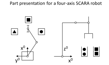
A SCARA robot is horizontally jointed. The tool yaw and tool pitch angles are fixed by the mechanical design so the tool always points downwards. The constraint is stronger than the five-axis case, because the approach vector is not merely confined to a plane, it is pinned to a single direction:
Substituting into the previous equation we get:
Now, components and are permanently zero. We are free to pick , , and , which are 4 numbers matching the 4 axes.
Axes 1, 2 and 3 are the major axes that position the tool tip. Axis 4 is the minor axis that orients the tool byrotating the sliding vector about the vertical.
Inverse Kinematics of a Four-Axis SCARA Robot
Given target configuration vector , we are tasked to find the joint variables that achieves this target vector. The forward map is:
Here are the complete algorithm: