Source
Adapted from my own handwritten and hand-typed notes from Year 1 to Year 3 of my EEE degree
Multiplexer
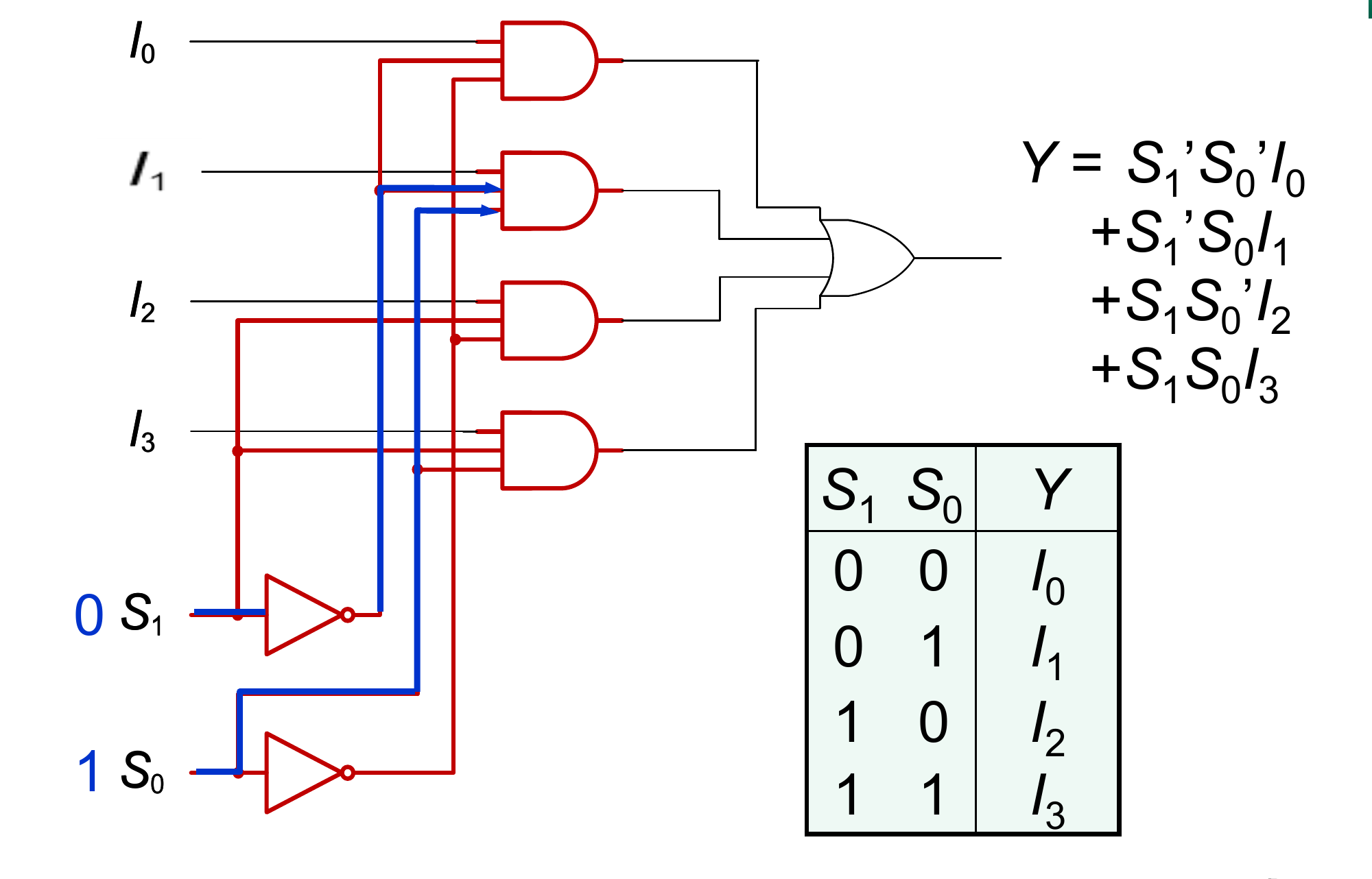
A multiplexer (MUX), or data selector, routes one of many input lines to a single output. With data inputs it needs select lines.
4-to-1 MUX:
| 0 | 0 | |
| 0 | 1 | |
| 1 | 0 | |
| 1 | 1 |
MSI Multiplexers
Common chips:
- 74150: 16-to-1
- 74151: 8-to-1 with strobe and outputs and
- 74153: dual 4-to-1
- 74157: quad 2-to-1
A 16-to-1 MUX can be built from two 74151s: the MSB enables the top chip when and the bottom chip when , and the outputs are combined with an OR (or NAND of the outputs).
A quad 2-to-1 MUX switches a whole 4-bit word with one select line:
MUX as a Function Generator
With variables on the select lines, an -to-1 MUX implements any function directly from the truth table: tie each data input to 0 or 1 to match the output column.
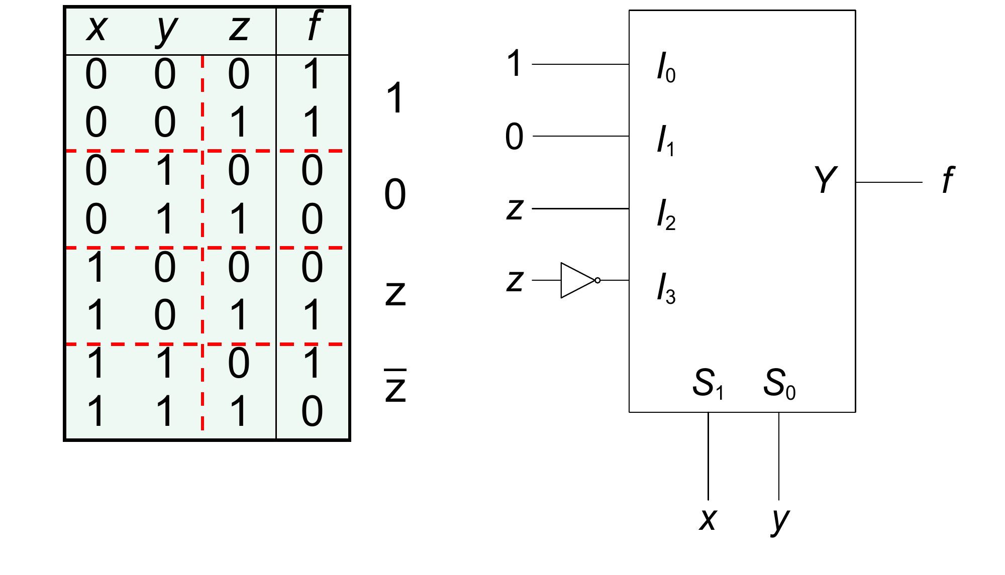
A smaller MUX also works. Put variables on the select lines and feed each data input with 0, 1, the last variable, or its complement.
Example, with a 4-to-1 MUX (, ):
| for | Data input | |
|---|---|---|
| 00 | 1, 1 | |
| 01 | 0, 0 | |
| 10 | 0, 1 | |
| 11 | 1, 0 |
Demultiplexer
A demultiplexer (DMUX) does the reverse: one data input is sent to one of outputs chosen by select lines. For a 1-to-4 DMUX, for the selected and all other outputs are 0.
A decoder with an enable is a DMUX: connect the data to the enable pin and use the decoder inputs as the select lines. When the selected output goes high, when every output stays low.